12
MODEL
ONIZ
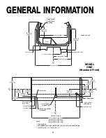
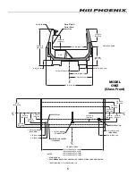
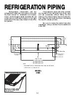
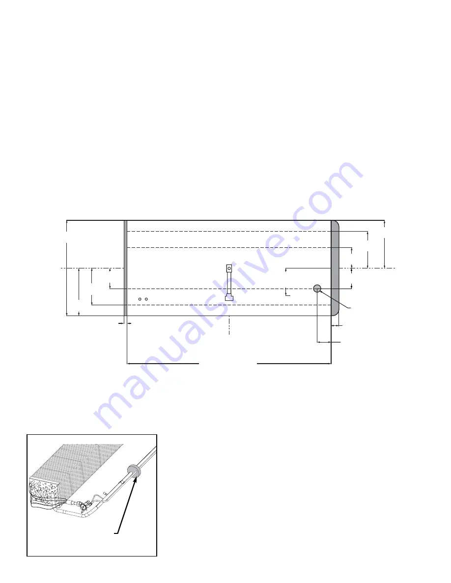
REFRIGERATION PIPING
Refrigeration components and the
refrigeration outlet hole are located to provide
the best access for installation and mainte-
nance. As the diagram below indicates the coil
outlet hole is positioned forward on the right
hand side of the case, fully visible in front of the
fan plenum.
The expansion valve and other controls
are located on the left-hand side of the case
and are accessible without lifting the fan
plenum. The control cluster may be reached by
only lifting the left hand deck pan minimizing
the need to unload product.
Be sure to reseal the outlet hole after
installation, using a canned foam sealant and
white RTV
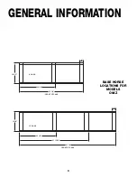
C
L
C
L
C
L
45 in
[114.2 cm]
22 1/2 in
[57.1 cm]
17 3/8 in
[44.1 cm]
9 11/16 in
[24.6 cm]
1 1/2 in [3.8 cm]
{FLAT END}
FRONT OF CASE
12 15/16 in
[32.9 cm]
**
22 1/2 in
[57.1 cm]
17 3/8 in
[44.1 cm]
9 11/16 in
[24.6 cm]
3 11/16 in [9.4 cm]
{WRAP END}
NOTES:
** RECOMMENDED STUB-UP CENTERLINE FOR ELECTRICAL AND HUB DRAINS
z
SUCTION LINE - 7/8", LIQUID LINE - 1/2"
72 in [182.9 cm] {6' case}
96 in [243.8 cm] {8' case}
120 in [304.8 cm] {10' case}
144 in [365.8 cm] {12' case}
REFRIGERATION
6 1/2 in [16.5 cm]
9 5/8 in
[24.4 cm]
REMOVE SHIPPING BLOCKS
REMOVE THE SHIPPING BLOCKS
THAT PROTECT THE REFRIGERATION
LINES DURING SHIPMENT BEFORE
OPERATING THE CASE.
Summary of Contents for ORIGIN2 ONIZ
Page 2: ......
Page 4: ......
Page 6: ...2...
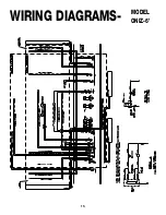
Page 19: ...15 WIRING DIAGRAMS MODEL ONIZ 6...
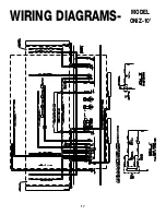
Page 20: ...16 WIRING DIAGRAMS MODEL ONIZ 8...
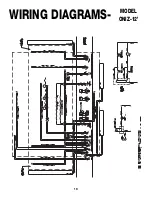
Page 21: ...17 WIRING DIAGRAMS MODEL ONIZ 10...


