background image


Network Traffic Speed Dome

·

Quick Start Guide


11 

1)


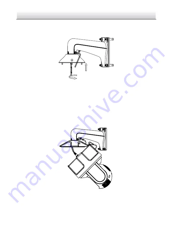
Align the head cover with the bracket, and rotate the head cover clockwise or 
anticlockwise, then secure the two lock screws with the wrench as shown in 
Figure 2-12. 


Figure 2-12


Install the Head Cover 

2)


Hang the safety rope to the speed dome and the hook on the bracket. 

3)


Hitch the speed dome onto the head cover with the hook on the back box. 

4)


Route the cables through the head cover and the bracket body, and connect the 
corresponding cables.   

Notes: 


Water-proof treatment is required for cable connectors. Refer to Section 2.5 

and 2.6 for details. 


After cable connection, put the cables into the head cover. 


Figure 2-13


Hang the Speed Dome 

5)


Align the back box of the speed dome with the head cover. 

6)


Tighten the lock screws to secure the speed dome with the wrench. 

Summary of Contents for iDS-2VS435-F840-EY

Page 1: ...Network Traffic Speed Dome Quick Start Guide i Network Traffic Speed Dome Quick Start Guide...

Page 2: ...rks and logos are the properties of Hikvision in various jurisdictions Other trademarks and logos mentioned are the properties of their respective owners LEGAL DISCLAIMER TO THE MAXIMUM EXTENT PERMITT...

Page 3: ...THOUT LIMITATION RIGHTS OF PUBLICITY INTELLECTUAL PROPERTY RIGHTS OR DATA PROTECTION AND OTHER PRIVACY RIGHTS YOU SHALL NOT USE THIS PRODUCT FOR ANY PROHIBITED END USES INCLUDING THE DEVELOPMENT OR PR...

Page 4: ...ng interference that may cause undesired operation EU Conformity Statement This product and if applicable the supplied accessories too are marked with CE and comply therefore with the applicable harmo...

Page 5: ...ing or a fire hazard Make sure that the plug is firmly connected to the power socket Make sure that the power has been disconnected before you wire install or dismantle the speed dome When the product...

Page 6: ...ser equipment is in using make sure that the surface of sensor will not be exposed to the laser beam Do not place the speed dome in extremely hot cold dusty or damp locations and do not expose it to h...

Page 7: ...d Dome 2 1 2 4 Type IV Speed Dome 3 2 Installation 4 2 1 Installing Type I Speed Dome 5 2 2 Installing Type II Speed Dome 7 2 3 Installing Type III Speed Dome 7 2 4 Installing Type IV Speed Dome 9 2 5...

Page 8: ...rk Cable Audio Cable Alarm Cable Video Cable RS 485 Cable Power Cord Optical Fiber Figure 1 1 Cable Interface Notes The cables vary depending on different speed dome models Make sure the speed dome is...

Page 9: ...Type I Speed Dome 1 2 2 Type II Speed Dome The memory card slot is in the speed dome drive as shown in Figure 1 3 Debug Reset Memory Card Slot Figure 1 3 Type II Speed Dome 1 2 3 Type III Speed Dome T...

Page 10: ...ck Start Guide 3 Memory Card Slot Figure 1 4 Type III Speed Dome 1 2 4 Type IV Speed Dome The memory card slot is on the camera module inside of the speed dome as shown in Figure 1 5 Memory Card Slot...

Page 11: ...f Do not drag the speed dome with its waterproof cables as shown in Figure 2 1 otherwise the waterproof performance is affected Figure 2 1 Do Not Drag the Cables For the speed dome that supports IR yo...

Page 12: ...ndent adapter is required if any other bracket is selected The dimension of pendant adapter is G1 1 2 2 1 Installing Type I Speed Dome Steps 1 Install the bracket 1 Drill four 12 holes for expansion s...

Page 13: ...stall the speed dome to the bracket 1 Hang the safety rope to the speed dome and the hook on the bracket 2 Route the cables of the speed dome through the bracket body and connect the corresponding cab...

Page 14: ...Note Installation for Type II Speed Dome is similar to installation for Type I Speed Dome Refer to section 2 1 Installing Type I Speed Dome 2 3 Installing Type III Speed Dome Steps 1 Install the brac...

Page 15: ...ove the protective cover Insert the memory card into the memory card slot Note The memory card can be installed in factory if you need Memory Card Slot Protective Cover Figure 2 7 Install the Micro SD...

Page 16: ...ective Film Figure 2 9 Secure the Speed Dome 2 4 Installing Type IV Speed Dome Steps 1 Install the bracket Note Refer to step 1 in section 2 1 Installing Type I Speed Dome for installing the wall moun...

Page 17: ...ticker Figure 2 10 Remove the Protective Sticker 2 Unscrew and disassemble the rear cover of the speed dome and insert the memory card into the slot on camera module Memory Card Slot Figure 2 11 Insta...

Page 18: ...the bracket 3 Hitch the speed dome onto the head cover with the hook on the back box 4 Route the cables through the head cover and the bracket body and connect the corresponding cables Notes Water pr...

Page 19: ...door you should use the waterproof accessory or tapes to waterproof the cables Otherwise the cables might get wet causing short circuit Align Figure 2 15 Install Waterproof Jacket Steps 1 Feed the net...

Page 20: ...allation surface Steps 1 Tear off the yellow release paper on the back of the water proof tape 2 Stretch the water proof tape to reach twice the initial length Stretch Stretch Initial Length Waterproo...

Page 21: ...re 2 18 Press the Water proof Tape 5 Wrap the water proof tape around the remaining unused cables tightly as the figure below Figure 2 19 Wrap the Unused Cables Note Make sure that all naked wires are...

Page 22: ...t Guide 15 2 7 Protective Measures for Outdoor Installation If the device is installed outdoors necessary protective measures should be taken to ensure safety Scan the following QR code to get protect...

Page 23: ...work Traffic Speed Dome Quick Start Guide 16 3 Activate and Access Network Camera Scan the QR code to get Activate and Visit Network Camera Note that mobile data charges may apply if Wi Fi is unavaila...

Page 24: ...Network Traffic Speed Dome Quick Start Guide 17 UD09156B B...

Reviews: