HIKVISION HiLook Series User Manual Download Page 8


2


Installation 

Before you start 


Make sure that the device in the package is in good 
condition and all the assembly parts are included. 


Make sure that all the related equipment is power-off 

during the installation. 


Check the specification of the products for the 

installation environment. 


Check whether the power supply is matched with 
your power output to avoid damage. 


Make sure the wall is strong enough to withstand 
three times the weight of the camera and the mount. 


If the product does not function properly, contact 

your dealer or the nearest service center. Do NOT 
disassemble the camera for repair or maintenance by 
yourself. 

2.1


Installation of Type I Camera 

2.1.1


Ceiling Mounting Without Junction Box 

Steps: 
1.


Rotate the camera to align one of the marks with 

the notch, and dissemble the camera. 

Mark

Notch


Figure 2-1


Align the Mark and the Notch 

2.


Pry the enclosure open with a flat object, for 

example, a coin, to dissemble the camera. 


Figure 2-2


Dissemble the Camera 
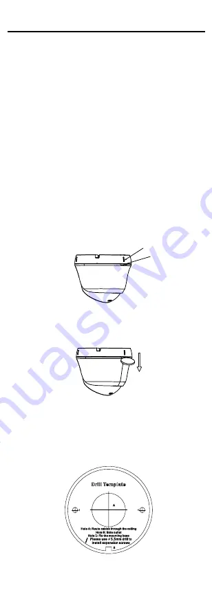
3.


Paste the drill template (supplied) to the place 
where you want to install the camera. 

4.


(Optional) For cement ceiling, drill the screw holes 
with a 5.5 mm drill and insert the supplied wall 

plugs. 


Figure 2-3


Drill Template 

5.


(Optional) Drill the cable hole, when the cables are 

routed through the ceiling. 

Summary of Contents for HiLook Series

Page 1: ...the models below Type Model Type I THC T129 PS Type II THC T129 MS Type III THC T229 MS Type IV THC B129 PS THC B129 MS Type V THC B229 MS This manual may contain several technical mistakes or printin...

Page 2: ...y invisible video products 2 The purpose of video products is to record real activities within a specific time and space and under specific conditions Therefore every user shall first reasonably defin...

Page 3: ...ive role in more aspects of social life Any abuse of video products in violation of human rights or leading to criminal activities are contrary to the original intent of technological innovation and p...

Page 4: ...red operation EU Conformity Statement This product and if applicable the supplied accessories too are marked with CE and comply therefore with the applicable harmonized European standards listed under...

Page 5: ...the device is firmly fixed if wall mounting or ceiling mounting is adopted If smoke odor or noise rise from the device turn off the power at once and unplug the power cord and then contact the service...

Page 6: ...rotection or turn on the supplement light only at a safe distance 0 3 m or in the area that is not directly exposed to the light when installing or maintaining the device Mark Description Table 0 1 Ma...

Page 7: ...ress and hold the switch button for 5 seconds to switch the video output Four kinds of video outputs are available TVI AHD CVI and CVBS 1 2 4 Overview of Type IV Camera DC12V IN Power Cord Video Cable...

Page 8: ...he nearest service center Do NOT disassemble the camera for repair or maintenance by yourself 2 1 Installation of Type I Camera 2 1 1 Ceiling Mounting Without Junction Box Steps 1 Rotate the camera to...

Page 9: ...75 Pan Position 0 to 360 Figure 2 6 3 Axis Adjustment 1 Rotate the enclosure to adjust the pan position 0 to 360 2 Move the main body up and down to adjust the tilt position 0 to 75 3 Rotate the main...

Page 10: ...ee M3 screws Figure 2 10 Combine the Junction Box Cover and Body 9 Connect the power cord and video cable and put the cables back into the junction box 10 Refer to step 9 of 2 1 1 Ceiling Mounting Wit...

Page 11: ...unction Box Steps 1 Paste the drill template supplied to the place where you want to install the camera 2 Optional For cement ceiling drill the screw holes with a 5 5 mm drill and insert the supplied...

Page 12: ...he main body up and down to adjust the tilt position 0 to 75 6 Rotate the main body to adjust the rotation position 0 to 360 8 Tighten the screw to finish the installation 2 2 5 Ceiling Mounting with...

Page 13: ...d put the cables back into the junction box 10 Refer to steps 5 7 and 8 of 2 2 4 Ceiling Mounting Without Junction Box to finish the installation 2 2 6 Wall Mounting Before you start You need to purch...

Page 14: ...ps 1 Paste the drill template supplied to the place where you want to install the camera 2 Optional For cement ceiling drill the screw holes with a 5 5 mm drill and insert the supplied wall plugs Figu...

Page 15: ...o the figure below Rotation Position 0 to 360 Tilt Position 0 to 75 Pan Position 0 to 360 Figure 2 30 3 Axis Adjustment 1 Rotate the enclosure to adjust the pan position 0 to 360 2 Move the main body...

Page 16: ...t to install the camera 2 Optional For cement wall drill the screw holes with a 5 5 mm drill and insert the supplied wall plugs Figure 2 33 Drill Template 3 Optional Drill the cable hole when the cabl...

Page 17: ...x Cover with Body 10 Refer to steps 7 and 11 of 2 3 1 Ceiling Mounting Without Junction Box to adjust the angle and finish installation 2 3 3 Wall Mounting Before you start You need to purchase a wall...

Page 18: ...o the place where you want to install the camera 2 Optional For cement ceiling drill the screw holes with a 5 5 mm drill and insert the supplied wall plugs Cable Hole Side Opening Scre w Hole Scre w H...

Page 19: ...unting are similar Following steps take wall mounting as an example Steps 1 Paste the drill template for junction box to the place where you want to install the camera 2 Optional For cement wall drill...

Page 20: ...the installation 2 5 Installation of Type V Camera 2 5 1 Ceiling Wall Mounting Without Junction Box Before you start The ceiling mounting and wall mounting are similar Following steps take ceiling mou...

Page 21: ...on 0 to 180 3 Loosen screw B to adjust the rotation position 0 to 360 7 Tighten the trim ring and screws to finish the installation 2 5 2 Ceiling Wall Mounting with Junction Box Installation of type I...

Page 22: ...BACK EXIT SAVE LEVEL EXIT FACTORY DEFAULT CANCEL CONFIRM Figure 3 2 Main Menu Overview 5 Click the direction buttons to control the camera 1 Click up down direction buttons to select menu options 2 C...

Page 23: ...when setting the AGC level ANTI BANDING ANTI BANDING is a camera setting that prevents the appearance of horizontal lines banding when photographing images in low frequency light and high brightness...

Page 24: ...duction Comparing with the general 2D digital noise reduction the 3D digital noise reduction function processes the noise between two frames besides processing the noise in one frame The noise will be...

Page 25: ...GS AUDIO LEVEL BACK EXIT SAVE EXIT ON 2 Figure 3 6 AUTO SETTINGS 3 6 FACTORY DEFAULT Click CANCEL to back to the main menu Click CONFIRM to reset all the settings to factory defaults 3 7 EXIT Move the...

Reviews: