background image

ERT-F2xxx DVR User Manual 

UM ERT-F2xxx 030118NA 

31 


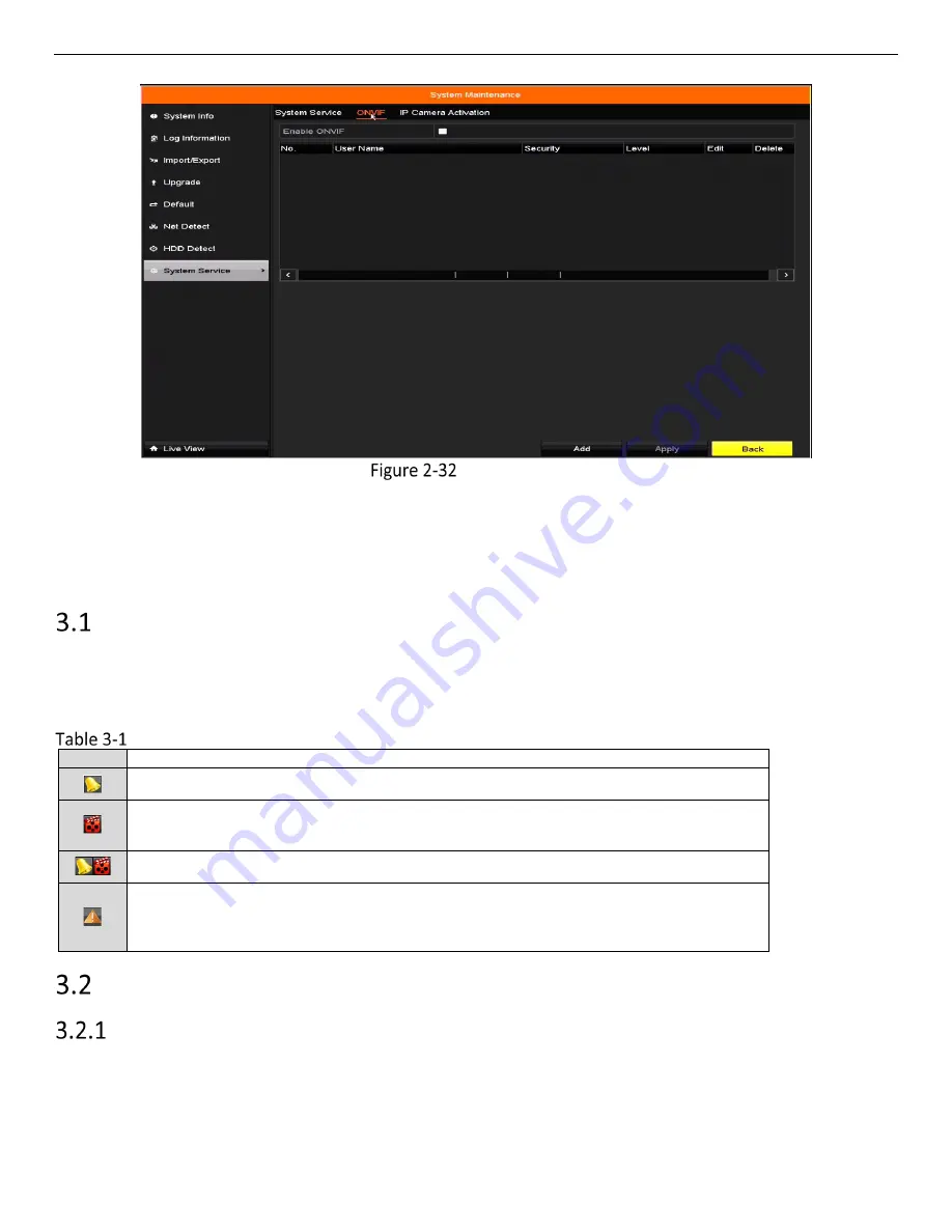
ONVIF Checkbox 

Chapter 3 Live View 

Live View displays the video image getting from each camera in real time.     

Live View Status Icons   

In live view mode, there are status icons at the upper-right of the screen for each channel, showing the status 

of the record and alarm in the channel, so that you can know whether the channel is recorded, or whether 

there are alarms occur as soon as possible. 


Description of Live View Icons 

Icons  Description 


Alarm (video loss, video tampering, motion detection, 

sensor alarm

, or VCA alarm) 


Record (manual record, continuous record, motion detection, 

sensor alarm

, or 

VCA alarm triggered record) 


Alarm & Record 


Event/Exception (motion detection, 

sensor alarm

, VCA alarm, or exception 

information appears at the lower-left corner of the screen. Refer to 

Chapter 8.8   

Setting Alarm Response Actions

 for details.) 


Operations in Live View Mode 

Right-Click Menu 

In live view mode, there are many functions provided. The functions are listed below. 
When the aux output is enabled, the main output cannot perform any operation, and you can do some basic 

operation on the live view mode for the Aux output. 

Summary of Contents for ERT-F204 Series

Page 1: ...ERT F204x ERT F208x ERT F216x Digital Video Recorder User Manual...

Page 2: ...this user manual under the guidance of professionals Trademarks Acknowledgement and other Hikvision trademarks and logos are the properties of Hikvision in various jurisdictions Other trademarks and...

Page 3: ...terference 2 This device must accept any interference received including interference that may cause undesired operation EU Conformity Statement This product and if applicable the supplied accessories...

Page 4: ...urge suppressors must not be daisy chained with power strips or other surge suppressors Maintenance Replace after a serious electrical event e g lighting blew out a transformer down the street Replace...

Page 5: ...le Models This manual is applicable to the models listed in the following table Series Model ERT F2xxx ERT F204x ERT F208x ERT F216x Symbol Conventions The symbols that may be found in this document a...

Page 6: ...t different capacity can be assigned to different channel Recording and Playback Holiday recording schedule configuration Continuous and event video recording parameters Multiple recording types manua...

Page 7: ...porting importing the GUID file Operation alarm exceptions and log recording and searching Manually triggering and clearing alarms Import and export of device configuration information Network Functio...

Page 8: ...ser Manual UM ERT F2xxx 030118NA 7 Upgrade by FTP server Development Scalability SDK for Windows and Linux system Source code of application software for demo Development support and training for appl...

Page 9: ...Editing the Connected IP Cameras and Configuring Customized Protocols 28 Enabling ONVIF 30 Chapter 3 Live View 31 Live View Status Icons 31 Operations in Live View Mode 31 Right Click Menu 31 Quick S...

Page 10: ...73 Auxiliary Playback Functions 74 Playing Back Frame by Frame 74 Fast View 75 Digital Zoom 75 File Management 76 Chapter 7 Backup 77 Backing up Record Files 77 Backing up by Normal Video Search 77 Ba...

Page 11: ...larms 118 Chapter 11 Camera Settings 120 Configuring OSD Settings 120 Configuring Privacy Mask 120 Configuring Video Parameters 121 Chapter 12 Device Management and Maintenance 123 Viewing System Info...

Page 12: ...tected the possible reason may be that the two devices are not compatible please refer to the recommended the device list from your provider Description of the Mouse Control Name Action Description Le...

Page 13: ...Ethernet interface 2 Power Supply 12 VDC power supply 3 VGA Interface DB9 connector for VGA output to display local video output and menu 4 HDMI Interface HDMI video output connector 5 USB Interface...

Page 14: ...e ground connection is working properly Starting Up the DVR Check the power supply is plugged into an electrical outlet It is HIGHLY recommended that an Uninterruptible Power Supply UPS be used in con...

Page 15: ...tivation password as you input it to ensure that it is input correctly Settings Admin Password We highly recommend that you create a strong password of your own choosing using a minimum of eight chara...

Page 16: ...assword interface Export GUID File Keep your GUID file safely for future password resetting When the device is activated the system pops up a message box to remind you to remember the password For an...

Page 17: ...vice is activated configure the device unlock pattern Set Unlock Pattern Use the mouse to draw a pattern among the nine dots on the screen Release the mouse when done Draw the Pattern Connect at least...

Page 18: ...t the pattern again Re set the Pattern Logging in via Unlock Pattern Only the admin user has the permission to unlock the device Configure the pattern first before unlocking Refer to Configuring the U...

Page 19: ...enter the normal login dialog box If the pattern you draw is different from the pattern you configured try again If you draw the wrong pattern more than five times the system will switch to the norma...

Page 20: ...admin user performs seven failed password attempts five attempts for the guest operator User Logout Purpose After logging out the monitor turns to live view mode To perform operations enter your user...

Page 21: ...rd Reset Password Select the GUID file from the USB flash drive and click Import to import the file to the device If you import the wrong GUID file seven times you will be not allowed to reset the pas...

Page 22: ...rt wizard when the device starts checkbox checked Enter the general settings interface to configure the VGA HDMI resolution system date and time and HDD initialization Initialize HDD Check to initiali...

Page 23: ...ice starts to search and add the matched cameras automatically Click OK when the cameras are added Manually Add Cameras Click Search to search for online IP cameras within the same network Click Add t...

Page 24: ...cameras are enabled by default no further action is required Adding and Connecting IP Cameras Activating IP Cameras Purpose Before adding the camera make sure the IP camera to be added is in active st...

Page 25: ...characters including at least three of the following categories upper case letters lower case letters numbers and special characters in order to increase the security of your product We also recommen...

Page 26: ...or go to Menu Camera Camera to enter the IP camera management interface Adding IP Camera Interface Online cameras in the same network segment will be detected and displayed in the camera list Select...

Page 27: ...ustom Adding IP Camera Interface You can edit the IP address protocol management port and other information of the IP camera to be added If the IP camera to add has not been activated activate it from...

Page 28: ...te the IP camera Play connected camera s live video Camera connected For the added IP cameras the Security status shows the security level of the password of camera strong password weak password and r...

Page 29: ...Channel Port 1 If the connected device is an encoding device with multiple channels you can choose the channel to connect by selecting the channel port no in the drop down list 2 Click OK to save the...

Page 30: ...rotocol in the custom adding IP camera interface to enter the protocol management interface Protocol Management Interface There are 16 customized protocols provided in the system you can edit the prot...

Page 31: ...nsfer protocol for the custom protocol Port Set the port no for the custom protocol Path Set the resource path for the custom protocol E g ch1 main av_stream The protocol type and the transfer protoco...

Page 32: ...Description Alarm video loss video tampering motion detection sensor alarm or VCA alarm Record manual record continuous record motion detection sensor alarm or VCA alarm triggered record Alarm Record...

Page 33: ...erfaces to define the main and auxiliary output interfaces The priority level for the main and aux output is HDMI VGA When both the HDMI and VGA are connected the HDMI is used as main output and the V...

Page 34: ...n set the image parameters such as brightness contrast saturation and hue Image Settings Customize Live View Strategy can be selected to set strategy including Real time Balanced and Fluency Live View...

Page 35: ...ings available in this menu include Video Output Interface Designates the output for which to configure the settings Only VGA HDMITM is selectable by default Live View Mode Designates the display mode...

Page 36: ...annel number to display the channel on the window If you do not want the camera to be displayed on the live view interface click the corresponding to stop it You can also click the icon to start live...

Page 37: ...ERT F2xxx DVR User Manual UM ERT F2xxx 030118NA 36 Stream Type Settings Click Apply to save the settings Optional Click Copy to copy the stream type settings of the current camera to other camera s...

Page 38: ...ter 4 PTZ Controls Configuring PTZ Settings Purpose Follow the procedure to set the PTZ parameters Configure the PTZ parameters before controlling the PTZ camera Go to Menu Camera PTZ PTZ Settings Cli...

Page 39: ...ustomizing Presets Purpose Follow the steps to set the Preset location you want the PTZ camera to point to when an event takes place Go to Menu Camera PTZ PTZ Settings Use the directional button to wh...

Page 40: ...option in the right click menu to show the PTZ control panel Choose Camera in the drop down list Click the button to show the general settings of the PTZ control PTZ Panel General Click to enter the...

Page 41: ...responding key point Speed defines the speed the PTZ will move from one key point to the next Click Add to add the next key point to the patrol Click OK to save the key point to the patrol To delete a...

Page 42: ...Stop Patrol to stop calling it Customizing Patterns Purpose Patterns can be set by recording the PTZ movement Call the pattern to make the PTZ move according to the predefined path Go to Menu Camera...

Page 43: ...nt panel or click the PTZ Control icon in the quick setting bar or select the PTZ option in the right click menu to show the PTZ control panel Click the button to show the general settings of the PTZ...

Page 44: ...ar scan and is in HIKVISION protocol Purpose Follow the procedure to call the linear scan in the predefined scan range Click PTZ in the lower right corner of the PTZ setting interface or press the PTZ...

Page 45: ...l from predefined preset 1 to preset 32 in order after the park time Undefined presets will be skipped Park Patrol 1 The dome starts move according to predefined patrol 1 path after the park time Park...

Page 46: ...PTZ Panel Description of the PTZ panel icons Icon Description Icon Description Icon Description Direction button and auto cycle button Zoom Focus Iris Zoom Focus Iris The speed of the PTZ movement Lig...

Page 47: ...ty such as transmission stream type resolution etc Before You Start Make sure that an HDD has been installed If not install and initialize an HDD Menu HDD General HDD General Check the storage HDD mod...

Page 48: ...ax Bitrate Range Recommend are not configurable Enabling it helps to ensure high video quality with a lowered bitrate The function is available only for IP cameras that support a H 264 stream Click Mo...

Page 49: ...y of the HDD Record Audio Check the checkbox to enable or disable audio recording Video Stream Main stream and sub stream are selectable for recording When you select sub stream you can record for a l...

Page 50: ...ing types are marked in different color icons Continuous Scheduled recording Event Recording triggered by all event triggered alarm Motion Recording triggered by motion detection Alarm Recording trigg...

Page 51: ...l Day checkbox blank and set the Start End time Up to eight periods can be configured for each day Time periods cannot overlap Select the record type in the drop down list To enable Motion Alarm M A m...

Page 52: ...ent Draw the Schedule Click Apply to validate the settings Optional To use the settings for other channels click Copy and choose the channel to copy to Click Apply to save the settings Configuring Mot...

Page 53: ...with the mouse To set motion detection for the entire area shot by the camera click Full Screen To clear the motion detection area click Clear By default Dynamic Analysis for Motion is enabled When m...

Page 54: ...he upper level menu Exit the Motion Detection menu Edit the Motion Detection Record Schedule For detailed configuration information Configuring Alarm Triggered Recordings Alarm triggered recordings ar...

Page 55: ...pe Check the Enable checkbox Click Settings Alarm Settings Choose the alarm triggered recording channel Check the checkbox to select channel Click Apply to save settings Click OK to back to the upper...

Page 56: ...recording triggered by the line crossing detection and intrusion detection alarm events Go to Menu Camera VCA VCA Settings Configure the detection rules for the line crossing detection or intrusion d...

Page 57: ...ual record Using manual record you need to manually cancel the record The manual recording is prior to the scheduled recording Go to Menu Manual or press the REC SHOT button on the front panel Manual...

Page 58: ...llow the steps to configure the record schedule on holiday for that year You may want to have different plan for recording on holiday Enter the Record setting interface Menu Record Holiday Holiday Set...

Page 59: ...ce Enter Record Schedule settings interface to edit the holiday recording schedule Files Protection Purpose You can lock the recording files or set the HDD property to Read only to protect the record...

Page 60: ...all the record files related to the playback channels Click to pop up the file management interface Click Locked File to check and export the locked files Locked File Management In the File Management...

Page 61: ...Search to show the results Export Search Result Protect the record files Find the record files you want to protect and then click the icon which will turn to indicating that the file is locked Incompl...

Page 62: ...per level menu You cannot save any files to a read only HDD To save files to the HDD change the property to R W If there is only one HDD and it is set to Read only the DVR can t record any files Only...

Page 63: ...upported Instant Playback by Channel Choose a channel in live view mode and click the button in the quick setting toolbar In instant playback mode record files recorded only during the last five minut...

Page 64: ...ck Playback by Time Purpose Play back video files recorded in specified time duration Multi channel simultaneous playback and channel switch are supported Go to Menu Playback Select Normal Smart in th...

Page 65: ...ing Click to start playing the continuous recorded files Playback Interface Use the toolbar on the bottom of the playback interface to control playing progress Playback Interface Toolbar of Playback C...

Page 66: ...Time Bar Scaling Previous Next period Play the time bar in 30 minutes default Play the time bar in 1 hour Play the time bar in 2 hours Play the time bar in 6 hours Play the time bar in 24 hours Refer...

Page 67: ...n event triggered recording Motion Detection Click and then hold the mouse on the image to draw the mouse to set the detection area manually You can also click the button to set the full screen as the...

Page 68: ...earched out by event type e g alarm input motion detection and VCA Go to Menu Playback Select the Event in the drop down list on the top left side Set the major type to Alarm Input Motion or VCA as th...

Page 69: ...sult information Refer to the right side bar for the results Select a result item and click to play back the file Pre play and post play can be configured Enter the Synch Playback interface to select...

Page 70: ...playing back by tag Go to Menu Playback Search and play back the record file s Refer to Chapter 6 1 1 for detailed information about searching for and playing back record files Interface of Playback...

Page 71: ...wn list in the Playback interface Choose channels edit the start time and end time and click Search to enter the Search Result interface Interface of Playback by Tag You can enter keywords into the te...

Page 72: ...select the previous or next tag Refer to Table 6 1 for the description of buttons on the toolbar Playing Back by System Logs Purpose Play back record file s associated with channels after searching sy...

Page 73: ...e Choose a log with record file and click to enter Playback interface If there is no record file at the time point of the log the message box No result found will pop up Result of System Log Search Pl...

Page 74: ...to Menu Playback Select the External File in the drop down list on the top left side The files are listed in the right side list You can click to refresh the file list Select and click to play the fi...

Page 75: ...age segments for playback E g if there are video files existing between 16 00 and 22 00 and the 6 screen display mode is selected then it can play the video files for 1 hour on each screen simultaneou...

Page 76: ...ayback of one frame Fast View Hold the mouse down and drag on the time bar to get a fast view of the video files Enter the playback interface and start to play the video files Playback Interface Use t...

Page 77: ...ips locked files and tags you have added in the playback mode Enter the playback interface Click on the toolbar to enter the file management interface File Management You can view saved video clips lo...

Page 78: ...HDDs Go to Menu Export Normal Select the cameras to search Set search condition and click Search to enter the search result interface The matched video files are displayed in Chart or List display mo...

Page 79: ...the files or you can select recording files you want to back up and click Export to enter the Export interface If the inserted USB device is not recognized do the following 1 Click Refresh 2 Reconnect...

Page 80: ...Purpose Back up event related record files using USB devices USB flash drives USB HDDs USB writer SATA writer or eSATA HDD Quick Backup and Normal Backup are supported Go to Menu Export Event Select t...

Page 81: ...rpose You may select video clips in playback mode to export directly during Playback using USB devices USB flash drives USB HDDs USB writer SATA writer Enter the Playback interface refer to Chapter 6...

Page 82: ...rt interface Storage Device Management Backup device management 1 Click New Folder to create a new folder in the backup device 2 Select a record file or folder in the backup device and click the butto...

Page 83: ...detection area s and drag the sensitivity bar to set sensitivity By default motion detection is enabled and configured in full screen 2 Click and set alarm response actions Motion Detection Setup Inte...

Page 84: ...day of the week up to eight time periods can be set within each day Click Apply to save the settings Time periods cannot repeat or overlap Set Arming Schedule of Motion Detection Click Handling to set...

Page 85: ...larm Select the Alarm Input tab to enter the Alarm Input Settings interface Alarm Status Interface of System Configuration Set up the handling action of the selected alarm input 1 Check Enable and cli...

Page 86: ...Apply to save the settings Select Arming Schedule to set the arming schedule of handling actions Set Arming Schedule of Alarm Input Choose a day of the week a maximum of eight time periods can be set...

Page 87: ...ut To set handling action of another alarm input repeat the above steps or you can click the Copy button on the Alarm Input Setup interface and check the checkbox of alarm inputs to copy the settings...

Page 88: ...handling actions 1 Select the Arming Schedule tab to set the channel s arming schedule 2 Choose one day of the week up to eight time periods can be set within each day 3 Click Apply to save the settin...

Page 89: ...o tampering handling action of the channel 1 Check Enable Video Tampering Detection 2 Drag the sensitivity bar to set a proper sensitivity level Use the mouse to draw an area you want to detect video...

Page 90: ...nitoring audible warning etc Go to Menu Camera VCA Select the camera to configure the VCA Select the VCA detection type to Line Crossing Detection Check Enable to enable this function Click to configu...

Page 91: ...save the rule settings and return to the line crossing detection settings interface Set Line Crossing Detection Rules Click and set two points in the preview window to draw a virtual line You can use...

Page 92: ...bject in the defined detection area is longer than the set time the alarm will be triggered Sensitivity Range 1 100 Click and drag the slider to set the detection sensitivity The value defines the siz...

Page 93: ...owing examples HDD Full The HDD is full HDD Error Writing HDD error or unformatted HDD Network Disconnected Disconnected network cable IP Conflicted Duplicated IP address Illegal Login Incorrect user...

Page 94: ...ify Surveillance Center Upload Picture to FTP Trigger Alarm Output and Send Email Event Hint Display When an event or exception occurs a hint can be displayed on the lower left corner of the live view...

Page 95: ...set by going to Menu Configuration Live View Full Screen Monitoring Dwell Time Auto switch will terminate once the alarm stops and you will be taken back to the Live View interface Select the channel...

Page 96: ...onfiguration Alarm Alarm Output Select an alarm output and set the alarm name and dwell time Click Schedule to set the alarm output arming schedule If Manually Clear is selected in the Dwell Time drop...

Page 97: ...ggering or Clearing Alarm Output Manually Purpose A sensor alarm can be triggered or cleared manually If Manually Clear is selected in the dwell time drop down list of an alarm output the alarm can be...

Page 98: ...C Type IPv4 Address IPv4 Gateway MTU and DNS Server If the DHCP server is available you can click the DHCP checkbox to automatically obtain an IP address and other network settings from that server Th...

Page 99: ...vate the function The Service Terms interface pops up as below Service Terms Create the verification code and enter the code in the Verification Code text field Check the The Hik Connect service will...

Page 100: ...and you should check the checkbox before enabling it Optional Check Custom and input the Server Address Optional Check Enable Stream Encryption After this feature is enabled the verification code is r...

Page 101: ...w hik connect com and the Hik Connect Mobile Client User Manual for adding the device to Hik Connect and more operation instructions After configuration you can access and manage the DVR with the mobi...

Page 102: ...rver Address for DynDNS i e members dyndns org 2 In the DVR Domain Name text field enter the domain obtained from the DynDNS Web site 3 Enter the User Name and Password registered in the DynDNS Web si...

Page 103: ...e Ensure the network connection of the PC running the FTP server and the device is valid and correct Run the FTP server on the PC and copy the firmware into the corresponding directory of your PC Refe...

Page 104: ...send the alarm event or exception message to the host when an alarm is triggered The remote alarm host must have the CMS Client Management System software installed The Alarm Host IP refers to the IP...

Page 105: ...ote IE access Configure More Settings Click Apply to save and exit the interface Configuring E Mail Purpose The system can be configured to send an e mail notification to all designated users if an al...

Page 106: ...ttings Interface Configure the following e mail settings Enable Server Authentication optional Check the checkbox to enable the server authentication feature User Name The user account of sender s e m...

Page 107: ...iguring NAT Purpose Two ways are provided for port mapping to realize the remote access via the cross segment network UPnP and manual mapping UPnP Universal Plug and Play UPnP can permit the device to...

Page 108: ...our demand by clicking to activate the External Port Settings dialog box 1 Select Manual in the Mapping Type drop down list 2 Click to activate the External Port Settings dialog box Configure the exte...

Page 109: ...port in the Forwarding interface Go to Menu Configuration Network Select NAT to enter the port mapping interface Leave the Enable UPnP checkbox unchecked Click to activate the External Port Settings...

Page 110: ...ternal port value and other required contents Each item should correspond with the device port including server port http port RTSP port and https port Setting Virtual Server Item The above virtual se...

Page 111: ...ugh the network detection function including network delay packet loss etc Testing Network Delay and Packet Loss Go to Menu Maintenance Net Detect Click the Network Detection tab to enter the Network...

Page 112: ...in Figure 9 22 Click Refresh if the connected local backup device cannot be displayed If the backup device cannot be detected check whether it is compatible with the DVR Format the backup device if th...

Page 113: ...checking result If the message box pops out with other information instead of this one click Network to show the quick setting interface of the network parameters Checking Network Statistics Purpose...

Page 114: ...ERT F2xxx DVR User Manual UM ERT F2xxx 030118NA 113 Check the bandwidths of the IP Camera Remote Live View Remote Playback Net Receive Idle and Net Send Idle Click Refresh to get the latest status...

Page 115: ...se Option 1 Initialize HDD from the Startup Wizard When the device starts up the Setup Wizard can guide you to configure basic settings In the General settings interface check Initialize HDD to initia...

Page 116: ...s been initialized the status of the HDD will change from Uninitialized to Normal HDD Status Changes to Normal Initializing the HDD will erase all data on it Configuring Quota Mode Purpose Each camera...

Page 117: ...with the same quota settings You can click the IP Camera checkbox to select all cameras Click OK to finish the Copy settings and go back to the Storage Mode interface Click Apply to apply the setting...

Page 118: ...can choose the self test types Short Test Expanded Test or Conveyance Test Click Start to start the S M A R T HDD self evaluation To use the HDD even when S M A R T checking has failed check the Cont...

Page 119: ...ure the HDD error alarms when the HDD status is Uninitialized or Abnormal Go to Menu Configuration Exceptions Set the Exception Type to HDD Error on the drop down list Click the checkbox s to select t...

Page 120: ...ERT F2xxx DVR User Manual UM ERT F2xxx 030118NA 119 When Trigger Alarm Output is selected you can also select the alarm output to be triggered from the list below Click Apply to save the settings...

Page 121: ...by clicking the checkbox Select the Date Format Time Format and Display Mode OSD Configuration Interface Use the mouse to click and drag the text frame on the preview window to adjust the OSD positio...

Page 122: ...can be adjusted The configured privacy mask zones on the window can be cleared by clicking the corresponding Clear Zone1 4 icons on the right side of the window or click Clear All to clear all zones S...

Page 123: ...ue Set the Enable Rotate function to Clockwise 270 degrees or OFF If OFF is selected the image is restored to original Set the Mirror Mode to Left Right Up Down Center or OFF If OFF is selected the im...

Page 124: ...Info Camera Record Alarm Network and HDD tabs to view the device information XXXXXXXXXXXXXX XXXXXXXXXXXXXXXXXXXXXXXXXXXXXXXX XXXXXXXXXXXXXXX Device Information Interface Searching and Exporting Log F...

Page 125: ...files will be displayed on the list as shown below Log Search Results Up to 2 000 log files can be displayed each time Click the button of each log or double click it to view its detailed information...

Page 126: ...w Folder to create a new folder in the backup device or click Format to format the backup device before log export Connect the backup device to the DVR before operating log export Importing Exporting...

Page 127: ...kup device Enter a password for the file Export Encryption Password Window Click OK to save the file To import a configuration file select the file from the selected backup device and click Import Aft...

Page 128: ...pgrade menu as shown in Figure 12 8 Local Upgrade Interface Select the update file from the backup device Click Upgrade to start upgrading After the upgrading is complete reboot the DVR to activate th...

Page 129: ...s Go to Menu Maintenance Default Restore Defaults Select the restore type from the following three options Restore Defaults Restore all parameters except the network including IP address subnet mask g...

Page 130: ...Configure the following settings Language The default language used is English Resolution Configure the VGA resolution and HDMI resolution respectively Time Zone Select the time zone Date Format Sele...

Page 131: ...ttings Interface Check the checkbox before the Auto DST Adjustment item or manually check the Enable DST checkbox and then choose the DST period date Configuring More Settings for Device Parameters Go...

Page 132: ...the current operation menu to live view screen after 5 minutes of menu inactivity Menu Output Mode You can choose the menu display on different video outputs By default only HDMI VGA is selectable Cl...

Page 133: ...setting the password monthly or weekly can better protect your product Level Set the user level to Operator or Guest Different user levels have different operating permission Operator The Operator use...

Page 134: ...Settings Interface Set the operating permission of Local Configuration Remote Configuration and Camera Configuration for the user Local Configuration Local Log Search Searching and viewing logs and s...

Page 135: ...trolling the alarm output Remote Advanced Operation Remotely operating HDD management initializing HDD setting HDD property upgrading system firmware clearing I O alarm output Remote Shutdown Reboot R...

Page 136: ...be deleted from the list as shown in Figure 1 3 Figure 1 3 User List Click to delete the selected user account Editing a User For the added user accounts you can edit the parameters Go to Menu Configu...

Page 137: ...esponding parameters Operator and Guest You can edit the user information including user name password permission level and MAC address Check the Change Password checkbox if you want to change the pas...

Page 138: ...rly Especially in a high security system resetting the password monthly or weekly can better protect your product Edit the unlock pattern for the admin user account 1 Check the Enable Unlock Pattern c...

Page 139: ...Internet Protocol Suite to notify a domain name server to change in real time ad hoc the active DNS configuration of its configured hostnames addresses or other information stored in DNS Hybrid DVR A...

Page 140: ...en the input mode of monitor must be the HDMITM input And if not please modify the input mode of monitor Check if the fault is solved by the step 1 to step 3 If it is solved finish the process If not...

Page 141: ...sufficient bandwidth Verify the network is connected Connect the DVR and PC with the RS 232 cable Open the Super Terminal software and execute the ping command Input ping IP e g ping 172 6 22 131 Simu...

Page 142: ...a Verify the network between IP camera and DVR is stable When the IP camera is offline connect PC and DVR with the RS 232 cable Open the Super Terminal use the ping command and keep sending large data...

Page 143: ...rom our company for further processing Live view stuck when video output locally Possible Reasons Poor network between DVR and IP camera and there exists packet loss during the transmission The frame...

Page 144: ...cket loss Simultaneously press Ctrl and C to exit the ping command Verify the network between the DVR and PC is connected Open the cmd window in the Start menu or you can press Windows R shortcut key...

Page 145: ...standard of the IP camera is supported by the DVR DVR supports G722 1 and G711 standards and if the encoding parameter of the input audio is not one of the previous two standards you can log in the IP...

Page 146: ...process If not contact an engineer from our company for further processing No record file found in the DVR local HDD and prompt No record file found Possible Reasons The time setting of system is inc...

Reviews: