background image

ECI-B64Z2 Quick Start Guide 

QSG ECI-B64Z2 041018NA 

3.2


Activate the Camera 

Activate the camera by setting a strong password. Activation via web browser, activation via 

SADP, and activation via client software are supported. Activation via SADP software and 

web browser will be used as examples to introduce camera activation.   

Note:   

Refer to the Network Camera User Manual for activation via client software.   

3.2.1


Activation via Web Browser 

Steps: 

1.


  Power the camera on. Connect the camera to your computer or the switch/router that 

your computer connects to. 

2.


  Input the IP address into the address bar of the Web browser, and press 

Enter

 to enter 

the activation interface. 

Notes: 


The camera’s default IP address is 192.168.1.64.   


The computer and the camera should belong to the same subnet.   


For cameras that have DHCP enabled by default, use the SADP software to search for the 

IP address. 


Activation Interface (Web) 

Figure 3-3

3.


Create and input a password. 

STRONG PASSWORD RECOMMENDED 

– We highly recommend creating a strong 

password of your own choosing (using a minimum of eight characters, including 
upper case letters, lower case letters, numbers, and special characters) in order to 
increase the security of your product. We recommend regularly resetting your 
password on a weekly or monthly basis, especially in high security systems. 


4.


Confirm the password. 

5.


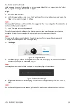
Click 

OK 

to save the password and enter the live view interface. 

Summary of Contents for ECI-B64Z2

Page 1: ...Network Bullet Camera ECI B64Z2 Quick Start Guide ...

Page 2: ... due to firmware updates or other reasons Please find the latest version in the company website http overseas hikvision com en Please use this user manual under the guidance of professionals Trademarks Acknowledgement and other Hikvision trademarks and logos are the properties of Hikvision in various jurisdictions Other trademarks and logos mentioned below are the properties of their respective ow...

Page 3: ...t into an outlet on a circuit different from that to which the receiver is connected Consult the dealer or an experienced radio TV technician for help FCC Conditions This device complies with part 15 of the FCC Rules Operation is subject to the following two conditions 1 This device may not cause harmful interference 2 This device must accept any interference received including interference that m...

Page 4: ...rload may cause over heating or a fire hazard Make sure that the plug is firmly connected to the power socket When the product is mounted on a wall or ceiling the device shall be firmly fixed If smoke odor or noise rise from the device turn off the power at once and unplug the power cable and then please contact the service center Cautions Make sure the power supply voltage is correct before using...

Page 5: ...capacitor of the equipment shall be replaced regularly according to their average enduring time The average time varies because of differences between operating environment and using history so regular checking is recommended for all the users Please contact your dealer for more details Improper use or replacement of the battery may result in hazard of explosion Replace with the same or equivalent...

Page 6: ...ble Water Resistant Jacket Optional 5 3 Camera LAN Configuration 6 3 1 Wiring 6 3 2 Activate the Camera 7 3 2 1 Activation via Web Browser 7 3 2 2 Activation via SADP Software 8 Modify the IP Address 8 3 3 4 Access via Web Browser 9 5 Hik Connect 11 5 1 Enable Hik Connect for Use with Cameras 11 5 2 Enable Hik Connect Service via SADP Software 11 5 2 1 Enable Hik Connect via a Web Browser 12 5 3 A...

Page 7: ...view of Type I Camera Figure 1 1 Description Table 1 1 No Description 1 Front Cover 2 Sun Shield 3 Lens 4 IR LED 5 Memory Card Slot 6 Reset Button 7 Camera Body 8 Bracket 9 Network Interface 10 Power Interface 11 CVBS Interface Note Press RESET for 10 s when the camera is powering on or rebooting to restore the default settings including the user name password IP address port no etc ...

Page 8: ...IR reflection Make sure that there is no reflective surface that is too close to the camera lens The IR light from the camera may reflect back into the lens which may cause reflection 2 1 Memory Card Installation Note A microSD memory card is not included with the camera You will need to purchase one separately This series of cameras supports memory card installation Different camera types share s...

Page 9: ...ing Steps 1 Stick the supplied drill template to the wall or ceiling where you intend to install the camera 2 Drill screw holes in the wall or ceiling according to the drill template Ceiling Mounting 1 1 1 1 2 2 2 2 1 Screw Hole for Bracket 2 Screw Hole for Mounting Base Ø 100 mm Ø 36 mm 8 Ø 5 mm Drilling Holes in the Wall Ceiling Figure 2 5 3 To route the cables through the wall or ceiling drill ...

Page 10: ...ess via Web Browser sections to check whether the image is at an optimum angle If not adjust the surveillance angle Pan Adjustment Steps 1 Loosen lock screw 1 2 Adjust the panning position of the camera The adjusting range is from 0 to 360 3 Tighten lock screw 1 Tilt Adjustment Steps 1 Loosen lock screw 2 2 Adjust the tilting position of the camera The adjustment range is from 0 to 90 3 Tighten lo...

Page 11: ...on the monitoring screen 3 Loosen the zoom lever and move the lever between T Tele and W Wide in order to obtain the desired angle of view 4 Tighten the zoom lever 5 Loosen the focus lever and move the lever between F Far and N Near to obtain the optimum focus 6 Tighten the focus lever 7 Install the sun shield and the front cover back onto the camera D C12V I N Zoom Focus Lever Zoom and Focus Adju...

Page 12: ...dcap 5 Water Resistant Rubber Gasket 6 Lock Nut 7 Network Cable from Router Switch Steps 1 Feed the plugless network cable through the lock nut water resistant rubber gasket the rubber gasket inset ridge must face the water resistant endcap and the water resistant endcap 2 Crimp an RJ 45 network plug onto the end of the cable making sure to insert the twisted pairs of wires in the correct order 3 ...

Page 13: ...Accessory Installation Figure 2 11 3 Camera LAN Configuration Note The use of products with Internet access carries inherent security risks In order to avoid network attacks and information leakage strengthen your own network protection If the product does not work properly contact your dealer or the nearest service center for help 3 1 Wiring Connect the camera to network as follows Network Cable ...

Page 14: ...e Web browser and press Enter to enter the activation interface Notes The camera s default IP address is 192 168 1 64 The computer and the camera should belong to the same subnet For cameras that have DHCP enabled by default use the SADP software to search for the IP address Activation Interface Web Figure 3 3 3 Create and input a password STRONG PASSWORD RECOMMENDED We highly recommend creating a...

Page 15: ...ssword STRONG PASSWORD RECOMMENDED We highly recommend creating a strong password of your own choosing using a minimum of eight characters including upper case letters lower case letters numbers and special characters in order to increase the security of your product We recommend regularly resetting your password on a weekly or monthly basis especially in high security systems Note You can enable ...

Page 16: ...to the same subnet as your computer by either modifying the IP address manually or by checking the Enable DHCP checkbox Modify the IP Address Figure 3 5 Note Hik Connect can be enabled during activation Refer to Chapter 5 1 for detailed information 4 Input the admin password and click Modify to complete IP address modification SADP supports batch IP address modification Refer to the SADP user manu...

Page 17: ... configure the device accounts and user operator permissions properly Delete the unnecessary accounts and user operator permissions Note The device IP address gets locked if the admin user performs seven failed password attempts five attempts for the user operator 4 Click Login Login Interface Figure 4 1 5 Install the plug in before viewing the live video and managing the camera Follow the install...

Page 18: ...Web browser 5 2 Enable Hik Connect Service via SADP Software Steps 1 Check the Enable Hik Connect checkbox 1 For the Activate the Device page that appears during camera activation refer to Chapter 3 2 2 2 For the Modify Network Parameters page that appears while modifying the IP address refer to Chapter 3 3 2 Create or change the verification code Verification Code Setting SADP Figure 5 1 Note The...

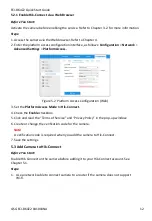
Page 19: ...ss Platform Access Configuration Web Figure 5 2 3 Set the Platform Access Mode to Hik Connect 4 Check the Enable checkbox 5 Click and read the Terms of Service and Privacy Policy in the pop up window 6 Create or change the verification code for the camera Note A verification code is required when you add the camera to Hik Connect 7 Save the settings 5 3 Add Camera to Hik Connect Before You Start E...

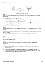
Page 20: ...le Hik Connect on your camera Forgotten verification codes can be recovered in the Platform Access configuration page via the web browser 4 Follow prompts to set up the network connection and add the camera to your Hik Connect account Note For detailed information refer to the Hik Connect user manual Initialize the Memory Card 5 4 Note The microSD memory card is not included with the camera and mu...

Page 21: ...ECI B64Z2 Quick Start Guide QSG ECI B64Z2 041018NA 14 ...

Reviews: