background image

Auxiliary Care Radar • User Manual 


Chapter 1 Product Introduction 

Introduction 

Based on the 60 GHz frequency band, auxiliary care radar (hereinafter referred to as “device”) 
adopts FMCW, MIMO, beamforming, micro-Doppler feature extraction, and other technologies. It 
can detect the vital signs, including person, breath, heartbeat, etc. 

The device can be installed above the bed in the bedroom, and the non-contact detection will 
cover the bed. It can obtain the information, including the time in the bed, the time out of the bed, 
breath rate, heart rate, times of movements, etc., and help to analyze the sleep quality and health 
of the human body. 

Key Feature 


No privacy disclosure. 


Remote and non-contact detection. 


Outputs the real-time breath rate and heart rate of the human body. 


Detects and outputs the information that if the human body is in the bed to the connected 
client software. Counts the time in the bed and the time out of the bed. 


Detects and outputs the human body movements to the connected client software, and counts 
the times of movements. 


Small size, beautiful structure, and easy installation. 
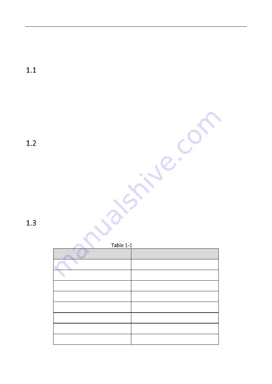
Specification 

Refer to the table below for the device specification. 


Specification 

Parameters 

Values 

Working Frequency 

60 to 64 GHz 

Modulation Wave 

FMCW 

Frequency Span 

3.5 GHz 

Horizontal FoV 

-45° to +45° 

Vertical FoV 

-45° to +45° 

Range Resolution 

0.0435 m 

Detection Range 

0.2 to 2.7 m 

Breath/Heart Rate Resolution 

0.08 Hz 

Summary of Contents for DS-TDSB00-EKH

Page 1: ...0 Auxiliary Care Radar User Manual...

Page 2: ...CLUDING AMONG OTHERS DAMAGES FOR LOSS OF BUSINESS PROFITS BUSINESS INTERRUPTION OR LOSS OF DATA CORRUPTION OF SYSTEMS OR LOSS OF DOCUMENTATION WHETHER BASED ON BREACH OF CONTRACT TORT INCLUDING NEGLIG...

Page 3: ...ides additional information to emphasize or supplement important points of the main text Indicates a potentially hazardous situation which if not avoided could result in equipment damage data loss per...

Page 4: ...Overview 2 Cables Description 2 Installation Requirements 3 Chapter 2 Software Instruction 4 Device Connection 4 2 1 1 Connection via Wi Fi 4 2 1 2 Connection via RS 485 5 Parameter Settings 5 2 2 2 R...

Page 5: ...health of the human body Key Feature No privacy disclosure Remote and non contact detection Outputs the real time breath rate and heart rate of the human body Detects and outputs the information that...

Page 6: ...nsion and appearance overview Dimension unit mm Appearance Cables Description Refer to the table below for the cables description Data Cycle 50 ms Communication Interface RS 485 Wi Fi Working Voltage...

Page 7: ...Attach the wires to the wall The valid detection range is up to 2 2 m bed Refer to the figure below for the device installation overview Installation Overview Set the device parameters and adjust the...

Page 8: ...radar via Wi Fi Before You Start Power on the radar 12 V Connect your computer to the radar AP hotspot SSID format IRS60_xxxx Default password abcd1234 Use ping command to test if the computer is conn...

Page 9: ...t Set BaudRate as 115200 Stop bit as 1 and Data bit as 8 No parity Set Radar Address Radar Address refers to the RS 485 communication sub device address 0 refers to the broadcast address that covers a...

Page 10: ...after SoftVersion to read the software version Click set the address code and click Set to edit the sub device address The address code range is 1 to 255 Make sure the device connected address is the...

Page 11: ...ode The radar will be standby and stop transmitting If the radar is powered off and does not receive wakeup command after powered on again then it will still be standby mode Awake If the radar is powe...

Page 12: ...on Open the software Press F1 button on the keyboard Menu Page Enter IP Address and Radar Port IP address 192 168 4 1 radar port 6666 Click Connect Click Browse to select the firmware to be upgraded S...

Page 13: ...pplication Upgrade Click Confirm Click Start Update Upgrade Radar Network Configuration You can set the radar network Open IRS60 5 Radar PC tool Press F2 button on the keyboard Enter IP Address and Po...

Page 14: ...figuration Click Connect Set Work Mode as 3 Click Set Set AP Router SSID and AP Router PWD AP Router SSID means the router name AP Router PWD means the router password Set DHCPC as 0 off Set IP Netmas...

Page 15: ...Auxiliary Care Radar User Manual 11 AP SSID means the Wi Fi name AP PWD means the Wi Fi password Set AP Click Set Set Device ID as an integer range 1 to 999999999 Set Device Information...

Page 16: ...nual 12 Set data report type as 0 Set service IP as Hikcentral Pro service IP Set service PORT as 20000 Set radar debug PORT as 6666 Set radar Passthrough data PORT as 20000 Set report interval as 0 C...

Page 17: ...0...

Reviews: