background image

Mobile Network Video Recorder User Manual 

64 

12.10 Configure Arming Schedule and Linkage Actions 

Step 1


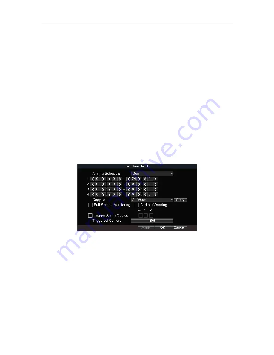
Click Handle to set the arming schedule and alarm linkage actions. 

Step 2


Select the day from Arming Schedule dropdown list. 

Step 3


Set the arming period for selected day. 

Step 4


(Optional) Copy the current settings to other days in the week. 

Step 5


Check to enable linkage actions. 


Full Screen Monitoring 

When an alarm is triggered, the local monitor displays the video image from the alarming 
channel configured for full screen monitoring. 


Audible Warning 

Trigger an audible beep when an alarm is detected. 


Trigger Alarm Output 

Trigger an alarm output when an alarm is detected. 

Step 6


Click OK


Figure 12-10


Linkage Action 

12.11 Configure Detection Area 

Step 1


Click Area Settings

Step 2


Drag to draw detection area. 

Step 3


Optionally, right click to delete areas or set detection sensitivity. 

Step 4


Right click and select Exit

Summary of Contents for DS-MP7516 Series

Page 1: ...Mobile Network Video Recorder User Manual 0 Mobile DVR User Manual UD07123N...

Page 2: ...hapter 3 Start Up Device 23 3 1 Startup 23 3 2 Activation 23 Chapter 4 Network 25 4 1 Set Local Network 25 4 2 Connect Wireless Network 25 4 2 1 3G 4G Dialing 25 4 2 2 Set Wi Fi 26 4 2 3 Set Wi Fi AP...

Page 3: ...r in Settings 49 Chapter 9 Playback 51 9 1 Instant Playback 51 9 2 Play Video by File 51 Chapter 10 Platform 53 10 1 eHome 53 10 2 Guarding Vision 53 10 3 Register Device in Guarding Vision platform 5...

Page 4: ...ttings 73 15 6 Import Export Configuration File 74 15 6 1 Import Configuration File 74 15 6 2 Export Configuration File 74 15 7 Serial Port Settings 75 Chapter 16 Shut Down Device 77 16 1 Enable Sched...

Page 5: ...NO EVENT WILL OUR COMPANY ITS DIRECTORS OFFICERS EMPLOYEES OR AGENTS BE LIABLE TO YOU FOR ANY SPECIAL CONSEQUENTIAL INCIDENTAL OR INDIRECT DAMAGES INCLUDING AMONG OTHERS DAMAGES FOR LOSS OF BUSINESS...

Page 6: ...onditions 1 This device may not cause harmful interference 2 This device must accept any interference received including interference that may cause undesired operation EU Conformity Statement This pr...

Page 7: ...ols that may be found in this document are defined as follows Symbol Description Provides additional information to emphasize or supplement important points of the main text Indicates a potentially ha...

Page 8: ...oise rise from the device turn off the power at once and unplug the power cable and then please contact the service center Preventive and Cautionary Tips Before connecting and operating your device pl...

Page 9: ...10M 100M 1000M RJ45 Ethernet interface 3 USB 3 0 USB 3 0 interface 4 PWR Power indicator Solid green Device is powered on Solid red Device is standby RDY Ready indicator Solid green Device starts up...

Page 10: ...R receiver IR receiver for remote control 6 Dummy HDD lock Lock unlock the dummy HDD 7 SD card slot Slot for SD card No Name Description 1 CAN 2 CAN interface 2 RS 232 The left one is for debugging Th...

Page 11: ...erface 8 PoE 1 to 8 8 PoE interface 9 Network interface 1 10M 100M 1000M RJ45 Ethernet interface 10 I O 4 ch alarm input 2 ch alarm output 4 ch sensor in 1 ch pulse signal input 11 VGA VGA video outpu...

Page 12: ...a position with enough space Recommended installation space is shown in Figure 2 1 Figure 2 1 Recommended Installation Space 2 2 Install HDD Before You Start Prepare the tools and components for insta...

Page 13: ...llowing steps are only for reference Step 1 Insert the key and turn counterclockwise to unlock dummy HDD Figure 2 3 Unlock Dummy HDD Step 2 Unfasten the two screws of dummy HDD and pull dummy HDD out...

Page 14: ...y HDD Step 4 Place the first HDD into the dummy HDD with the PCB facing down Figure 2 6 Place HDD Step 5 Push the HDD along the direction shown in Figure 2 7 to connect HDD with socket of dummy HDD Fi...

Page 15: ...rder User Manual 14 Figure 2 8 Fix HDD Step 7 Repeat step 4 to 6 to install the secondary HDD in the other socket of dummy HDD Figure 2 9 Install the Other HDD Step 8 Reassemble the dummy HDD Figure 2...

Page 16: ...on 2 3 Install SIM Card Purpose Pluggable 3G 4G wireless communication module is designed for the device and you should install the SIM card to realize the wireless communication function Before You S...

Page 17: ...Wi Fi module Step 4 Press the yellow button on the 3G 4G slot and then pull the SIM card tray out Figure 2 14 Pull out SIM Card Tray Step 5 Place the SIM card on SIM card tray Figure 2 15 Place SIM c...

Page 18: ...and tighten the set screw 2 4 Install SD Card Before You Start Prepare the tools and components for installation Key to dummy HDD delivered with device SD card Figure 2 17 Tools Step 2 Insert the key...

Page 19: ...k Video Recorder User Manual 18 Figure 2 19 Unfasten Screws Step 4 Open the cover of SD card slot Figure 2 20 Open Cover Step 5 Insert SD card into SD card slot with gold contacts facing down till you...

Page 20: ...wise to lock dummy HDD Figure 2 22 Finish Installation 2 5 Alarm Input Output Connection 2 5 1 Alarm Input Connection The device adopts the high low level electrical signals triggering high level 6 to...

Page 21: ...own Delay Purpose The device starts up when the vehicle ignites and shuts down after the vehicle is off The vehicle ignition startup and shutdown are realized by the vehicle positive pole ignition swi...

Page 22: ...rmal vehicle power refers to the main power of the vehicle power supply system After the vehicle is off the normal vehicle power still provides direct current source for the other devices inside and g...

Page 23: ...Mobile Network Video Recorder User Manual 22 Figure 2 26 Timing On Off...

Page 24: ...into the dummy HDD lock Step 2 Rotate it clockwise to ON status Do not perform any operations during the startup process The startup process takes about 1 minute The system enters the live view interf...

Page 25: ...nd special characters in order to increase the security of your product And we recommend you reset your password regularly especially in the high security system resetting the password monthly or week...

Page 26: ...ce IP Address Subnet Mask Default Gateway DNS Server Address and Download Server IP Step 4 Optionally click Set of More Settings to enable disable LAN Sharing LAN Sharing Enable the function to share...

Page 27: ...More Settings 2 Select Bearing Mode 3 Enter APN Access Point Name Dial Number User Name and Password 4 Select Verification Protocol 5 Click OK Step 4 Click OK and reboot the device to activate the new...

Page 28: ...e Encryption Type and Key Step 5 Set the IP address and DNS server for Wi Fi network 1 Click Set of More Settings 2 Configure IP address and DNS parameters 3 Click OK Figure 4 4 IP DNS Settings for Wi...

Page 29: ...er devices are able to detect the SSID of the device Enable WiFi Hotspot Enable it to share the device s internet connection Other devices can access to internet via joining the hotspot Step 4 Click O...

Page 30: ...Menu Other Settings Firewall Figure 4 8 Firewall Settings Step 2 Optionally select Enable SSH Service to effectively prevent information leakage during remote management Step 3 Click Add Step 4 Enter...

Page 31: ...faces 5 1 Activate IP Camera Purpose Before adding an IP camera activate it by setting a password for it 5 1 1 Auto Activation Purpose Activate the IP camera by setting its password the same with the...

Page 32: ...ENDED We highly recommend you create a strong password of your own choosing Using a minimum of 8 characters including at least three of the following categories upper case letters lower case letters n...

Page 33: ...the device you can quickly add it Before you start Make sure the IP camera password is the same with the device Step 1 Go to Menu Other Settings IPC Settings Step 2 Select an online IP camera Step 3...

Page 34: ...customized protocols for them The system provides 16 customized protocols Step 1 Go to Menu Other Settings IPC Settings Step 2 Click Manually Add Step 3 Click Protocol Figure 5 6 Protocol Step 4 Edit...

Page 35: ...ile Network Video Recorder User Manual 34 Figure 5 7 Edit IP Camera 5 4 Delete IP Camera Step 1 Select an IP camera and click Delete Step 2 Click Yes on the pop up dialog box Figure 5 8 Delete IP Came...

Page 36: ...etc Step 1 Go to Menu Other Settings Camera Figure 6 1 Camera Settings Step 2 Select Camera to configure Step 3 Edit parameters as your desire Step 4 Optionally select the camera in Copy to dropdown...

Page 37: ...p 4 Edit the parameters Step 5 Click OK Step 6 Click OK in advanced settings interface Step 7 Click OK in camera settings interface 6 2 Set Privacy Mask Purpose The privacy mask can be used to protect...

Page 38: ...as Step 6 Right click and select Exit Step 7 Click OK in Advanced settings interface Step 8 Click OK in Camera settings interface 6 3 Set Mirror Type Purpose Set the mirror type of the image as left r...

Page 39: ...Mobile Network Video Recorder User Manual 38 Step 3 Select Mirror Type as required Step 4 Click OK in Advanced settings interface Step 5 Click OK in Camera settings interface...

Page 40: ...according to the actual needs Step 3 Configure the Preview Mode Dwell Time and Enable Audio Output Preview Mode Select the window division mode for live view Dwell Time The switch interval of the live...

Page 41: ...following steps Step 3 Click Set of Camera Order Step 4 Click of window 1 to select camera to display Step 5 Click of window 2 to select camera to display Step 6 Click to switch to next page Step 7 Re...

Page 42: ...f the PTZ parameters should be done before you control the PTZ camera Step 1 Go to Menu Other Settings PTZ Item Description Menu Enter the main menu of the system by right clicking the mouse Multi Scr...

Page 43: ...the same with those of the PTZ camera Step 4 Click OK 7 4 2 PTZ Control Panel In live view interface right click a PTZ camera and click PTZ on right click menu Figure 7 6 PTZ Control Panel Table 7 2 D...

Page 44: ...be initialized before it can be used Step 1 Go to Menu Storage Figure 8 1 Storage Management Step 2 Check the HDD to format Step 3 Click Format 8 1 2 Configure Overwrite Purpose The overwrite function...

Page 45: ...urpose Specify the percentage of picture partition among the whole storage capacity You can start capturing in eHome platform Step 1 Go to Menu Storage Figure 8 3 Storage Management Step 2 Enter Pictu...

Page 46: ...ndicators of reliability in the hopes of anticipating failures Step 1 Go to Menu Storage Figure 8 4 Storage Management Step 2 Select an HDD Step 3 Click S M A R T Info Figure 8 5 S M A R T Information...

Page 47: ...ity as Highest Higher Medium Low Lower or Lowest Frame Rate Frame rate refers to the frequency of the image frame after compression With other parameters constant reduce the video frame rate and you c...

Page 48: ...re Setting Figure 8 7 Motion Detection Settings Step 3 Check Motion Detection Step 4 Click Area Settings of Motion Detection Step 5 Edit area settings For details refer to 12 11 Configure Detection Ar...

Page 49: ...ng schedule Refer to 8 2 5 Configure Schedule for record settings Recording type must be alarm motion alarm or motion alarm 8 2 4 Configure Alarm Terminal Before you start Install an alarm terminal Fo...

Page 50: ...ording and then select the recording type from the drop down list Uncheck All Day customize the time period for recording and select the recording type for each time period Step 6 Click OK 5 recording...

Page 51: ...Mobile Network Video Recorder User Manual 50 Figure 8 11 Sensor In Settings Step 2 Set Triggering Level and Full Screen Monitoring for sensor in Step 3 Click OK...

Page 52: ...rch Mode as General Only the general video supports instant playback General Normal videos Step 3 Select Camera Step 4 Select Video Type Step 5 Specify Start Time and End Time Step 6 Click Play to pla...

Page 53: ...e General Normal videos Event Motion detection alarm motion alarm and motion alarm videos Step 3 Select Camera Step 4 Select Video Type Step 5 Specify Start Time and End Time Step 6 Click Search The m...

Page 54: ...the following parameters Server Address Type IP Address and Domain Name are selectable Server IP Enter the static IP address of iVMS server Port No The default value is 7660 Device Register ID The ID...

Page 55: ...Platform Step 3 Select Platform as Guarding Vision Step 4 Click OK and reboot the device to activate the new settings Step 5 Optionally go to Menu Status Platform to view the platform status 10 3 Reg...

Page 56: ...ep 1 Go to Menu Video Search Figure 11 1 Video Search Step 2 Select Search Mode General Normal videos Event Motion detection alarm motion alarm motion alarm videos Step 3 Select Camera Step 4 Select V...

Page 57: ...he status and the free space capacity of the connected backup device And you can also format the backup device Step 1 Go to Menu Maintenance Storage Figure 11 3 Backup Device Step 2 Select Backup Devi...

Page 58: ...t of More Setting Figure 12 1 Motion Detection Settings Step 3 Check Motion Detection Step 4 Set the area for motion detection For detailed steps refer to 12 11 Configure Detection Area Step 5 Set the...

Page 59: ...ing from 5 VDC to 6 VDC Step 5 Click Set of Schedule to set arming schedule For detailed steps refer to 12 10 Configure Arming Schedule and Linkage Actions Step 6 Check Linkage Action and click Set of...

Page 60: ...dwell time Step 5 Click Set of Schedule to set the arming schedule for alarm outputs For detailed steps refer to 12 10 Configure Arming Schedule and Linkage Actions Step 6 Click OK 12 4 Configure Alar...

Page 61: ...Step 2 Click Set of More Setting Figure 12 5 Video Loss Step 3 Check Video Loss Step 4 Set arming schedule and linkage actions For detailed steps refer to 12 10 Configure Arming Schedule and Linkage A...

Page 62: ...tampering alarm can be triggered only when the view of the camera is fully covered Step 5 Set arming schedule and linkage actions For detailed steps refer to 12 10 Configure Arming Schedule and Linkag...

Page 63: ...standards do not match Abnormal Recording No space for saving recorded files 12 8 Configure Satellite Positioning Purpose The built in GNSS module supports GPS Global Positioning System enabling devi...

Page 64: ...r obtaining and providing the acceleration speed in 3 axial directions Step 1 Go to Menu Basic Settings G Sensor Figure 12 9 G Sensor Settings Step 2 Select G sensor mode under Module RS 232 The G sen...

Page 65: ...ble linkage actions Full Screen Monitoring When an alarm is triggered the local monitor displays the video image from the alarming channel configured for full screen monitoring Audible Warning Trigger...

Page 66: ...her Settings User Figure 13 1 User Management Step 2 Click Add Figure 13 2 Add User Step 3 Enter User Name and Password and enter the same password in Confirm Step 4 Select the user permission level O...

Page 67: ...Step 1 Go to Menu Other Settings User Step 2 Select a user and click Delete Step 3 Click Yes in confirmation message box 13 3 Edit User Step 1 Go to Menu Other Settings User Step 2 Select a user and c...

Page 68: ...Figure 14 1 Display Settings Step 2 Edit parameters as required CVBS Output Standard NTSC or PAL are selectable Set it according to actual video input standard System Time Set it by adjusting year mon...

Page 69: ...ick OK in DST settings interface Step 7 Click OK in Display Settings 14 3 Configure NTP Step 1 Go to Menu Basic Settings Network Step 2 Click Set of More Settings Step 3 Click Set of NTP Figure 14 3 N...

Page 70: ...default device No is 255 It is not recommended to modify Device No Otherwise you need to enter the Device No on the remote control every time you use it CVBS Brightness Adjust video output brightness...

Page 71: ...llite positioning G Sensor alarm and WiFi Figure 15 1 Status 15 2 View System Information Go to Menu Maintenance Information to view the device name model serial No firmware version encoding version a...

Page 72: ...re 15 3 Upgrade Step 3 Click Upgrade to start upgrading and reboot the device to activate the new settings 15 3 2 Upgrade by Remote FTP server Before you start Ensure the network connection of the PC...

Page 73: ...tings 15 4 Log Operation 15 4 1 Search Log File Purpose The operation alarm exception and information of the device can be stored in log files which can be viewed and exported at any time Step 1 Go to...

Page 74: ...at any time Before you start Connect a backup device to the device Step 1 Go to Menu Maintenance Log Search Figure 15 6 Log Search Step 2 Search log files For detailed steps refer to 15 4 1 Search Lo...

Page 75: ...e The configuration files of one device can be imported to multiple device devices if they are to be configured with the same parameters Before you start Connect a backup device that contains the conf...

Page 76: ...can be configured by using software such as HyperTerminal The serial port parameters must be the same as of the device when connecting with the PC serial port Transparent Channel Connect a serial devi...

Page 77: ...Mobile Network Video Recorder User Manual 76 Step 3 Click OK...

Page 78: ...d Startup Shutdown Figure 16 1 Scheduled Startup Shutdown Step 3 Select the Date to set the schedule Step 4 Specify the startup time segments Two periods can be configured for each day And the time pe...

Page 79: ...e ranges from 0 to 6 hours Step 4 Optionally check Voltage Protect and select Voltage Limit Percent If the voltage of the device reaches the selected threshold the device will shut down automatically...

Page 80: ...1 Buttons Description Before you start Batteries 2 AAA must be installed before operation Figure 17 1 Remote Control Table 17 1 Description of the IR Remote Control Buttons No Name Description 1 Power...

Page 81: ...eserved 10 MENU Enter Main menu interface 11 PREV In live view switch screen mode as single screen or multi screen 12 Direction buttons Navigate between fields and items in menus In playback interface...

Page 82: ...number Step 5 Press ENTER on the remote control 17 2 3 Enter Contents in Text Field Step 1 Press Left Right to position the cursor in the text field Step 2 Press Enter to edit Step 3 Press Edit to del...

Page 83: ...ick the Area Settings button Step 2 Press the Edit key on the remote control and a red block appears on the screen Step 3 Press the Direction keys on the remote control to adjust the position of the r...

Page 84: ...location and time information in all weather and anywhere on or near the earth where there is an unobstructed line of sight to 4 or more GPS satellite G Sensor G sensor Gravity sensor can sense the c...

Page 85: ...d The motherboard or power functions abnormally In case of hardware failure please contact the supplier of the product Fail to connect 3G 4G Possible reasons for 3G 4G connection failure are as follow...

Page 86: ...ive when operating with the IR remote control a The batteries are installed correctly making sure that the polarities of the batteries are not reversed b The batteries are fresh and are not out of pow...

Page 87: ...Mobile Network Video Recorder User Manual 86 UD08343N...

Reviews: