


Network Video Recorder User Manual
122
12.8 Unattended Baggage Detection
Purpose
Unattended baggage detection function detects the objects left over in the pre-defined region such
as the baggage, purse, dangerous materials, etc., and a series of actions can be taken when the
alarm is triggered.
Step 1
Go to System > Event > Smart Event.
Step 2
Click Unattended Baggage.
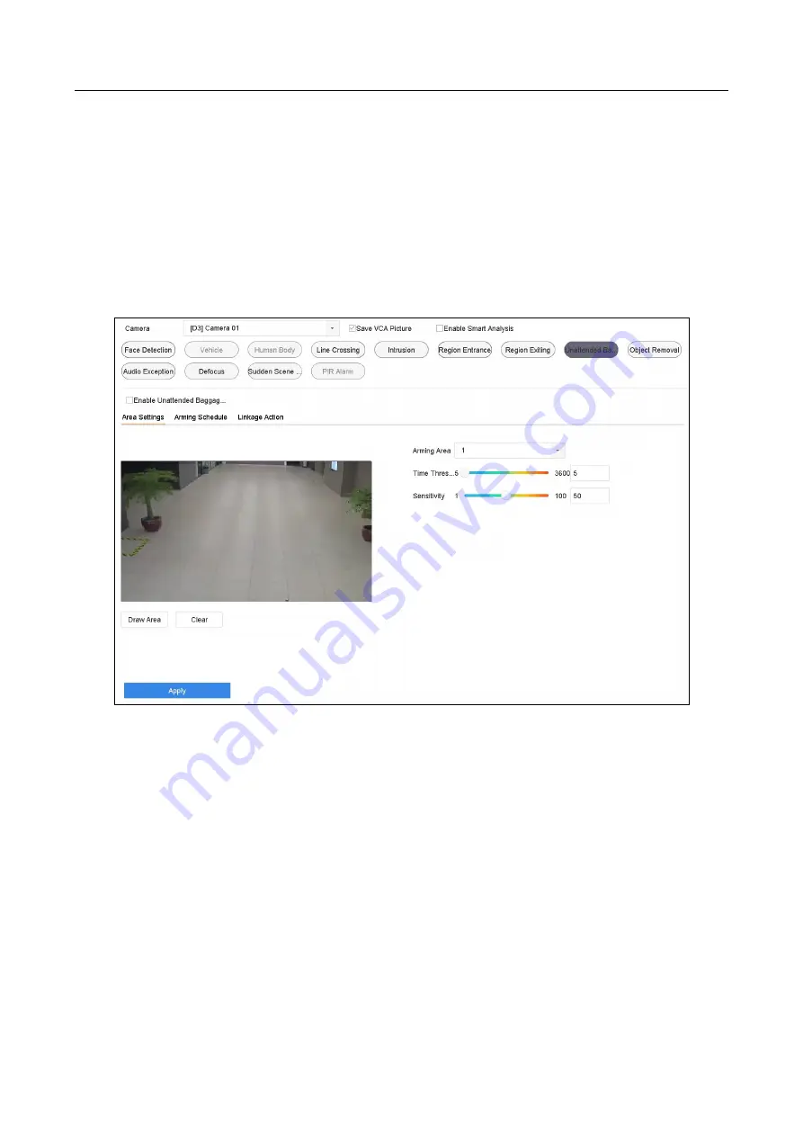
Figure 12-8
Unattended Baggage Detection
Step 3
Select a Camera to configure.
Step 4
Check Enable Unattended Baggage Detection.
Step 5
Optionally, check Save VCA Picture to save the captured pictures of unattended baggage
detection.
Step 6
Follow the steps to set the detection rules and detection areas.
1)
Select an Arming Region to configure. Up to 4 regions are selectable.
2)
Drag the sliders to set Time Threshold and Sensitivity.
Time Threshold: The time of the objects left over in the region. If the value is 10, alarm is
triggered after the object is left and stayed in the region for 10s. Its range is [5s-20s].


