background image

Quick Operation Guide of DS-7200HFHI-ST&SE Series DVR 

Front Panels 


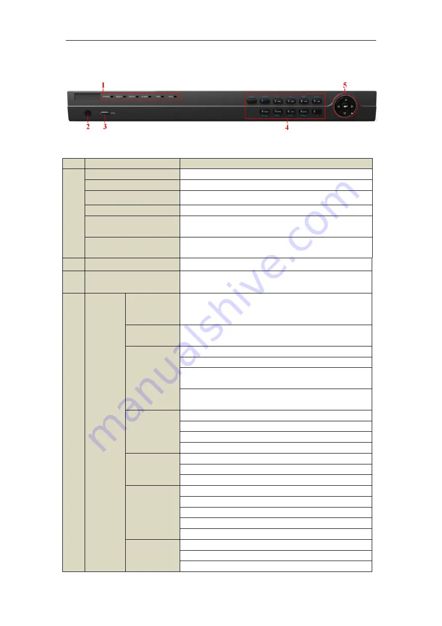
Front Panel of DS-7204HFHI-ST 

Description of Control Panel Buttons 

No. 

Name 

Function Description 

POWER 

Power indicator turns yellow once the power switch turns on. 

READY 

Ready indicator turns yellow when system is running. 

STATUS 

Status indicator turns red when SHIFT mode is on. 

ALARM 

Alarm indicator turns red when a sensor alarm is detected. 

HDD 

HDD indicator blinks red when data is being read from or written to 

HDD. 

TX/RX


TX/RX  indictor  blinks  yellow  when  network  connection  is 

functioning properly. 

IR Receiver


Receiver for IR remote. 

USB Interfaces 

Universal Serial Bus (USB) ports for additional devices such as 

USB mouse and USB Hard Disk Drive (HDD). 

Composite 

Keys 

SHIFT 

Switch between the numeric or letter input and functions of the 

composite keys. (Input letter or numbers when the light is out; 

Realize functions when the light is red.) 

1/MENU 

Enter numeral “1”;   

Access the main menu interface. 

2/ABC/F1 

Enter numeral “2”;   
Enter letters “ABC”;   

The F1 button when used in a list field will select all items in the 

list. 

In PTZ Control mode, it will turn on/off PTZ light and when the 

image is zoomed in, the key is used to zoom out. 

3/DEF/F2 

Enter numeral “3”;   
Enter letters “DEF”;   

The F2 button is used to change the tab pages. 

In PTZ control mode, it zooms in the image. 

4/GHI/ESC 

Enter numeral “4”; 
Enter letters “GHI”;   

Exit and back to the previous menu. 

5/JKL/EDIT 

Enter numeral “5”; 
Enter letters “JKL”; 

Delete characters before cursor; 

Check the checkbox and select the ON/OFF switch;   

Start/stop record clipping in playback. 

6/MNO/PLAY 

Enter numeral “6”; 

Enter letters “MNO”;   

Playback, for direct access to all-day playback interface. 

Summary of Contents for DS-7200HFHI-SE

Page 1: ...DS 7200HFHI ST SE Series DVR Quick Operation Guide UD 6L0202B0048A02 ...

Page 2: ...for rack mounting 2 Ensure there is ample room for audio and video cables 3 When installing cables ensure that the bend radius of the cables are no less than five times than its diameter 4 Connect both the alarm and RS 485 cable 5 Allow at least 2cm 0 75 inch of space between racks mounted devices 6 Ensure the DVR is grounded 7 Environmental temperature should be within the range of 10 º C 55 º C ...

Page 3: ... of DS 7200HFHI ST SE Series DVR 2 3 Connect the power cable to the HDD 4 Place the HDD on the bottom of the device and then fasten the screws on the bottom to fix the HDD 5 Re install the cover of the DVR and fasten screws ...

Page 4: ...te Keys SHIFT Switch between the numeric or letter input and functions of the composite keys Input letter or numbers when the light is out Realize functions when the light is red 1 MENU Enter numeral 1 Access the main menu interface 2 ABC F1 Enter numeral 2 Enter letters ABC The F1 button when used in a list field will select all items in the list In PTZ Control mode it will turn on off PTZ light ...

Page 5: ...vement of the PTZ camera ENTER The ENTER button is used to confirm selection in any of the menu modes It can also be used to tick checkbox fields In Playback mode it can be used to play or pause the video In single frame Playback mode pressing the button will advance the video by a single frame In Auto switch mode it can be used to stop start auto switch Note It is important to note that you must ...

Page 6: ...Quick Operation Guide of DS 7200HFHI ST SE Series DVR 5 3 USB Interfaces Universal Serial Bus USB ports for additional devices such as USB mouse and USB Hard Disk Drive HDD ...

Page 7: ... 3 AUDIO OUT RCA connector 4 VGA DB9 connector for VGA output Display local video output and menu 5 HDMI HDMI video output connector 6 USB Port Universal Serial Bus USB port for additional devices 7 Network Interface Connector for network 8 RS 485 Interface Connector for RS 485 devices 9 Power Supply DC 12V power supply 10 Power Switch Switch for turning on off the device 11 GND Gound ...

Page 8: ... hold the orange part of the pluggable block insert signal cables into slots and release the orange part Ensure signal cables are in tight 3 Connect pluggable block back into terminal block Note The RS 485 unit can be used as T and T when it s working in the output mode and R and R when it s working in the input mode We take the RS 485 connection of 7204HFHI SE as an example Rear Panel of DS 7204H...

Page 9: ...024 768 60 Hz Encoding resolution Main stream 1920 1080 1080P 1280 720 VGA 4CIF CIF Sub stream CIF QCIF QVGA Frame rate Main stream 1 16 fps full frame rate Sub stream 1 16 fps full frame rate Video bitrate 32 Kbps 16 Mbps Audio output 1 ch RCA Linear 1KΩ Audio bitrate 64 Kbps Dual stream Support Stream type Video Video Audio Synchronous playback 4 ch Playback resolution 1920 1080 1080P 1280 720 V...

Page 10: ...ression G 711u Audio input 4 ch RCA 2 0 Vp p 1 KΩ Two way audio in 1 ch RCA 2 0 Vp p 1 KΩ using the 1st channel of audio input Video Audio output HDMI VGA output 1920 1080 60 Hz 1080P 1280 1024 60 Hz 1280 720 60 Hz 1024 768 60 Hz Encoding resolution Main stream 1920 1080 1080P non real time 1280 720 VGA 4CIF CIF Sub stream CIF QCIF QVGA Frame rate Main stream 1 16 fps full frame rate Sub stream 1 ...

Page 11: ...nterface 1 standard RS 485 serial interface half duplex USB port 2 USB2 0 Alarm in out 4 1 optional General Power supply 12V DC Consumption without hard disk Max 15 W Working temperature 10 º C 55 º C 14 º F 131 º F Working humidity 10 90 Chassis Stand alone 1U chassis Dimensions W D H 315 230 45 mm 12 3 9 0 1 8 inch Weight 2 kg 4 4lb without hard disk ...

Page 12: ...te Bit Rate Storage Used 96K 42M 128K 56M 160K 70M 192K 84M 224K 98M 256K 112M 320K 140M 384K 168M 448K 196M 512K 225M 640K 281M 768K 337M 896K 393M 1024K 450M 1280K 562M 1536K 675M 1792K 787M 2048K 900M 4096K 1800M 8192K 3600M 16384K 7200M Note Please note that supplied values for storage space used is just for reference Storage space used is estimated by formulas and may have some deviation from...

Page 13: ... DVR Check the power supply is plugged into an electrical outlet It is HIGHLY recommended that an Uninterruptible Power Supply UPS be used in conjunction with the device Turn on the power switch on the rear panel the Power indicator LED on the front panel should be yellow To shut down the DVR 1 Enter the Shutdown menu Menu Shutdown 2 Select the Shutdown button 3 Click the Yes button 4 Turn off the...

Page 14: ...be the same with the resolution of the monitor screen 2 The Setup Wizard can walk you through some important settings of the DVR If you don t want to use the Setup Wizard at this time click the Cancel button You can also choose to use the Setup Wizard next time by leaving the Start wizard when DVR starts checkbox in checked status 3 Click Next button on the Wizard window to enter the Login window ...

Page 15: ...sword checkbox Enter the new password and confirm the password in the given fields 6 Click the Next button to enter the date and time settings window 7 After the time settings click Next button which will take you back to the Network Setup Wizard window 8 Click Next button after you having configured the network parameters which will take you to the HDD Management window ...

Page 16: ...camera status These icons include Live View Icons In the live view mode there are icons at the right top of the screen for each channel showing the status of the record and alarm in the channel so that you can find problems as soon as possible Indicating that there is an alarm or are alarms Alarm includes video loss tampering motion detection or sensor alarm etc Recording manual record schedule re...

Page 17: ...d be exactly the same as the PTZ camera parameters 4 Click Copy if you want to configure same settings to other PTZ cameras 5 Click the Apply button to save and exit the interface PTZ Control In the Live View mode you can press the PTZ Control button on the front panel or on the remote or choose the PTZ Control icon to enter the PTZ panel Description of the PTZ panel icons Icon Description Icon De...

Page 18: ... view menu Instant playback by channel Choose a channel under live view using the mouse and click the button in the shortcut operation menu Note Only record files recorded during the last five minutes on this channel will be played back All day Playback by channel 1 Enter the All day Playback menu Mouse right click a channel in live view mode and select All day Playback from the menu Front Panel p...

Page 19: ... can be used to control playing process The channel and time selection menu will display by moving the mouse to the right of the playback interface Just tick the channel or channels if you want to switch playback to another channel or execute simultaneous playback of multiple channels Backup Recorded files can be backed up to various devices such as USB flash drives USB HDDs or USB DVD writers To ...

Page 20: ...7200HFHI ST SE Series DVR 19 2 Enter Export interface choose backup device and click the Export button to start exporting 3 Check backup result Choose the record file in Export interface and click button to check it 0202001021128 ...

Reviews: