HIKVISION DS-7108NI User Manual Download Page 153

User Manual of WIFI Network Video Recorder 

152 

12.2


Configuring Quota Mode


Purpose: 

Each camera can be configured with allocated quota for the storage of recorded files. 

Steps: 

1.


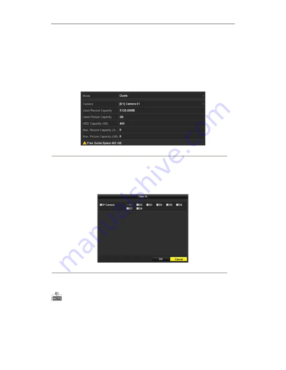
Enter the Storage Mode interface. 

Menu > HDD > Advanced 


Figure 12. 6


Storage Mode Settings Interface 


2.


Select a 

Camera 

to configure quota parameters. 

3.


Input the capacity in the text fields of 

Max. Record Capacity (GB)

4.


Repeat the steps above to configure for other cameras. 

Or copy the current camera settings to other cameras by clicking the 

Copy

 button to enter the Copy Camera 

menu, as shown in Figure 12. 7. 


Figure 12. 7


Copy Settings to Other Camera(s) 


5.


Click the 

OK 

button to save the settings and back to the Storage Mode interface. 

6.


Click the

 Apply

 button to apply the settings. 


If the quota capacity is set to 

0

, then all cameras will use the total capacity of HDD for record. 

Summary of Contents for DS-7108NI

Page 1: ...User Manual of WIFI Network Video Recorder 1 Network Video Recorder User Manual UD 6L0202D1984A01 ...

Page 2: ...nd logos mentioned below are the properties of their respective owners Legal Disclaimer TO THE MAXIMUM EXTENT PERMITTED BY APPLICABLE LAW THE PRODUCT DESCRIBED WITH ITS HARDWARE SOFTWARE AND FIRMWARE IS PROVIDED AS IS WITH ALL FAULTS AND ERRORS AND HIKVISION MAKES NO WARRANTIES EXPRESS OR IMPLIED INCLUDING WITHOUT LIMITATION MERCHANTABILITY SATISFACTORY QUALITY FITNESS FOR A PARTICULAR PURPOSE AND...

Page 3: ...he FCC Rules Operation is subject to the following two conditions 1 This device may not cause harmful interference 2 This device must accept any interference received including interference that may cause undesired operation EU Conformity Statement This product and if applicable the supplied accessories too are marked with CE and comply therefore with the applicable harmonized European standards l...

Page 4: ...he transmitter by Industry Canada To reduce potential radio interference to other users the antenna type and its gain should be so chosen that the equivalent isotropically radiated power e i r p is not more than that necessary for successful communication Conformé ment àla ré glementation d Industrie Canada le pré sent é metteur radio peut fonctionner avec une antenne d un type et d un gain maxima...

Page 5: ... unit as a result of dropping it may cause damage to the sensitive electronics within the unit Use the device in conjunction with an UPS if possible Power down the unit before connecting and disconnecting accessories and peripherals A factory recommended HDD should be used for this device Table 1 1 Recommended HDDs Manufacturer Type Capacity Seagate WD5000LUCT 500G Seagate WD10JUCT 1T Toshiba MQ01...

Page 6: ...Privacy mask Multiple PTZ protocols supported PTZ preset patrol and pattern Zooming in by clicking the mouse and PTZ tracing by dragging mouse HDD Management Two kinds of HDD capacity are selectable 500G and 1T Support S M A R T and bad sector detection HDD quota management different capacity can be assigned to different channel Recording and Playback Holiday recording schedule configuration Conti...

Page 7: ...ice configuration information Network Functions 1 self adaptive 10M 100M network interfaces is provided IPv6 is supported TCP IP protocol PPPoE DHCP DNS DDNS NTP SADP SMTP SNMP NFS and iSCSI are supported TCP UDP and RTP for unicast Auto Manual port mapping by UPnPTM Extranet access by HiDDNS and EZVIZ Cloud P2P Remote reverse playback via RTSP Support accessing by the platform via ONVIF Remote se...

Page 8: ...Using the Mouse in Live View 33 3 2 2 Quick Setting Toolbar in Live View Mode 34 3 3 Adjusting Live View Settings 37 Chapter 4 PTZ Controls 39 4 1 Configuring PTZ Settings 40 4 2 PTZ Control Panel 42 4 3 Setting PTZ Presets Patrols Patterns 43 4 3 1 Customizing Presets 43 4 3 2 Calling Presets 43 4 3 3 Customizing Patrols 44 4 3 4 Calling Patrols 45 4 3 5 Customizing Patterns 46 4 3 6 Calling Patt...

Page 9: ...7 2 Managing Backup Devices 89 Chapter 8 Alarm Settings 92 8 1 Setting Motion Detection Alarm 93 8 2 Setting Sensor Alarms 95 8 3 Detecting Video Loss Alarm 98 8 4 Detecting Video Tampering Alarm 100 8 5 Handling Exceptions Alarm 102 8 6 Setting Event Hint Display 105 8 7 Triggering or Clearing Alarm Output Manually 106 Chapter 9 VCA Alarm 107 9 1 Face Detection 108 9 2 Vehicle Detection 109 9 3 L...

Page 10: ...1 3 Checking Network Traffic 144 11 4 Configuring Network Detection 145 11 4 1 Testing Network Delay and Packet Loss 145 11 4 2 Exporting Network Packet 145 11 4 3 Checking the Network Status 146 11 4 4 Checking Network Statistics 147 Chapter 12 HDD Management 149 12 1 Initializing HDD 150 12 2 Configuring Quota Mode 152 12 3 Checking HDD Status 153 12 4 HDD Detection 154 12 5 Configuring HDD Erro...

Page 11: ...figuring DST Settings 173 15 3 Configuring More Settings for NVR 174 15 4 Managing User Accounts 175 15 4 1 Adding a User 175 15 4 2 Deleting a User 177 15 4 3 Editing a User 178 Chapter 16 Appendix 180 16 1 Glossary 181 16 2 Troubleshooting 182 16 3 Summary of Changes 188 16 4 List of Compatible IP Cameras 190 List of Hikvision IP Cameras 190 List of Third party IP Cameras 191 ...

Page 12: ...User Manual of WIFI Network Video Recorder 11 Chapter 1 Introduction ...

Page 13: ...nterface No Name Description 1 LAN Interface 1 3 3 RJ 45 10 100Mbps network interfaces for LAN Local Area Networks 2 WAN Interface 1 RJ 45 10 100 Mbps network interface for WAN Wide Area Networks 3 USB Interface Universal Serial Bus USB ports for additional devices such as USB mouse and USB writer 4 HDMI HDMI video output connector 5 POWER 12VDC Power supply ...

Page 14: ...ider The operation of the mouse Table 1 2 Description of the Mouse Control Name Action Description Left Click Single Click Live view Select channel and show the quick set menu Menu Select and enter Double Click Live view Switch between single screen and multi screen Click and Drag PTZ control pan tilt and zoom Video tampering privacy mask and motion detection Select target area Digital zoom in Dra...

Page 15: ...ard 1 Figure 1 4 Soft Keyboard 2 Description of the buttons on the soft keyboard Table 1 3 Description of the Soft Keyboard Icons Figure 1 5 Icon Description Icon Description Number English letter Lowercase Uppercase Backspace Switch the keyboard Space Positioning the cursor Exit Symbols Reserved ...

Page 16: ...User Manual of WIFI Network Video Recorder 15 Chapter 2 Getting Started ...

Page 17: ... supply is plugged into an electrical outlet It is HIGHLY recommended that an Uninterruptible Power Supply UPS be used in conjunction with the device During the starting up program a splash screen appears on the monitor Shutting down the NVR Steps 1 Enter the Shutdown menu Menu Shutdown Figure 2 1 Shutdown Menu 2 Click the Shutdown button 3 Click the Yes button 4 Unplug the power supply when the a...

Page 18: ...sword of your own choosing using a minimum of 8 characters including upper case letters lower case letters numbers and special characters in order to increase the security of your product And we recommend you reset your password regularly especially in the high security system resetting the password monthly or weekly can better protect your product 2 Click OK to save the password and activate the ...

Page 19: ...2 5 Start Wizard Interface Steps 1 If you don t want to use the setup wizard at that moment click the Exit button You can also choose to use the Setup Wizard next time by leaving the Start wizard when the device starts checkbox checked 2 Click the Next button to enter the Date and Time Settings interface Figure 2 6 Date and Time Settings 3 After the time settings click Next button which takes you ...

Page 20: ...s PPPoE and input Account and Password 5 Click Next button to enter WIFI settings interface Figure 2 8 WIFI Settings 6 Edit SSID and select Security Type Input Network Security Key if Security Type does not set as Disable 7 Click Next button which takes you to the General Network Configuration window ...

Page 21: ...gured the general network parameters Then you will enter the EZVIZ Cloud P2P interface Configure the EZVIZ Cloud P2P according to your needs Figure 2 10 EZVIZ Cloud P2P interface 9 Click Next button to enter the Advanced Network Parameter interface You can enable UPnP enable DDNS and set other ports according to your need ...

Page 22: ...IP Camera interface 13 Click Next button to enter the IP Camera Management interface 14 Click Search to search the online IP Camera and the Security status shows whether it is active or inactive Before adding the camera make sure the IP camera to be added is in active status If the camera is in inactive status you can click the inactive icon of the camera to set the password to activate it You can...

Page 23: ...of WIFI Network Video Recorder 22 Figure 2 13 IP Camera Management 15 Click Next button Configure the recording for the added IP Cameras Figure 2 14 Record Settings 16 Click OK to complete the startup Setup Wizard ...

Page 24: ...ork segment the Security status shows whether it is active or inactive Figure 2 15 IP Camera Management Interface 2 Click the inactive icon of the camera to enter the following interface to activate it You can also select multiple cameras from the list and click the One touch Activate to activate the cameras in batch Figure 2 16 Activate the Camera 3 Set the password of the camera to activate it U...

Page 25: ...ct the network cameras and save the video got from it So before you can get a live view or record of the video you should add the network cameras to the connection list of the device Before you start Establish the network connection between IPC and the NVR via wired or wireless network Wired network connect the Ethernet port of computer to the LAN interface of NVR And configure the IP address of c...

Page 26: ...e NVR Or you can click the One touch Adding button to add all cameras with the same admin password from the list Make sure the camera to add has already been actiavted by setting the admin password and the admin password of the camera is the same with the NVR Table 2 1 Explanation of the icons Icon Explanation Icon Explanation Edit basic parameters of the camera Add the detected IP camera The came...

Page 27: ...To add other IP cameras 1 Click the Custom Adding button to pop up the Add IP Camera Custom interface Figure 2 20 Custom Adding IP Camera Interface 2 You can edit the IP address protocol management port and other information of the IP camera to be added 3 Click Add to add the camera OPTION 2 Steps 1 Enter the Camera Management interface Menu Camera Camera Figure 2 21 Main Menu 2 Repeat the step 3 ...

Page 28: ...amera The camera is disconnected you can click the icon to get the exception information of camera Advanced settings of the camera Delete the IP camera Upgrade the connected IP camera Security Show the security status of the camera to be active inactive or the password strength strong weak risk 3 For the encoders with multiple channels only check the checkbox of Channel No in the pop up window as ...

Page 29: ...eters you can edit the IP address protocol and other parameters Figure 2 24 Edit the Parameters 2 Click OK to save the settings and exit the editing interface To edit advanced parameters Steps 1 Drag the horizontal scroll bar to the right side and click the icon Figure 2 25 Network Configuration of Camera 2 You can edit the Network information and the Password of the camera 3 Click Apply to save t...

Page 30: ...e URL uniform resource locator for getting main stream and sub stream The format of the URL is Type IP Address of the network camera Port Path Example rtsp 192 168 1 55 554 ch1 main av_stream Protocol Name Edit the name for the custom protocol Enable Substream If the network camera does not support sub stream or the sub stream is not needed leave the checkbox empty Type The network camera adopting...

Page 31: ...User Manual of WIFI Network Video Recorder 30 Figure 2 27 Protocol Setting 3 Choose the protocols you just added to validate the connection of the network camera ...

Page 32: ...User Manual of WIFI Network Video Recorder 31 Chapter 3 Live View ...

Page 33: ...us of the record and alarm in the channel so that you can know whether the channel is recorded or whether there are alarms occur as soon as possible Table 3 1 Description of Live View Icons Icons Description Alarm video loss video tampering motion detection alarm or VCA alarm Record manual record continuous record motion detection alarm record or VCA alarm triggered record Alarm Record Event Excep...

Page 34: ...e 3 2 1 Using the Mouse in Live View Table 3 2 Mouse Operation in Live View Name Description Menu Enter the main menu of the system by right clicking the mouse Single Screen Switch to the single full screen by choosing channel number from the drop down list Multi screen Adjust the screen layout by choosing from the drop down list Previous Screen Switch to the previous screen Next Screen Switch to ...

Page 35: ... Quick Setting Toolbar Icons Icon Description Icon Description Icon Description Enable Disable Manual Record Instant Playback Mute Audio on PTZ Control Digital Zoom Image Settings Face Detection Live View Strategy Information Close Instant Playback only shows the record in last five minutes If no record is found it means there is no record during the last five minutes Digital Zoom can zoom in the ...

Page 36: ...r 35 Figure 3 3 Digital Zoom Image Settings icon can be selected to enter the Image Settings menu Figure 3 4 Image Settings Preset You can set the image parameters like brightness contrast saturation and hue Figure 3 5 Image Settings Customize ...

Page 37: ...User Manual of WIFI Network Video Recorder 36 Live View Strategy can be selected to set strategy including Real time Balanced Fluency Figure 3 6 Live View Strategy ...

Page 38: ...utput Interface Designates the output to configure the settings for and only HDMITM is selectable Live View Mode Designates the display mode to be used for live view Dwell Time The time in seconds to dwell between switching of channels when enabling auto switch in live view Enable Audio Output Enable disable audio output for the selected video output Volume Adjust the volume of live view playback ...

Page 39: ... on the channel number to display the channel on the window If you do not want the camera to be displayed on the live view interface click the corresponding to stop it You can also click button to start live view for all the channels and click to stop all the live view 3 Click the Apply button to save the setting ...

Page 40: ...User Manual of WIFI Network Video Recorder 39 Chapter 4 PTZ Controls ...

Page 41: ...he PTZ parameters should be done before you control the PTZ camera Steps 1 Enter the PTZ Settings interface Menu Camera PTZ Figure 4 1 PTZ Settings 2 Click the PTZ Parameter Settings button to set the RS 485 parameters Figure 4 2 PTZ General Settings 3 Choose the camera for PTZ setting in the Camera drop down list 4 Enter the parameters of the PTZ camera ...

Page 42: ...User Manual of WIFI Network Video Recorder 41 All the parameters should be exactly the same as the PTZ camera parameters 5 Click Apply button to save the settings ...

Page 43: ...l mode the PTZ panel will be displayed when a mouse is connected with the device If no mouse is connected the icon appears in the lower left corner of the window indicating that this camera is in PTZ control mode Figure 4 3 PTZ Panel Table 4 1 Description of the PTZ panel icons Icon Description Icon Description Icon Description Direction buttons and auto cycle button Zoom Focus Iris Zoom Focus Iri...

Page 44: ...e the directional button to wheel the camera to the location where you want to set preset and the zoom and focus operations can be recorded in the preset as well 3 Enter the preset No 1 255 in the preset text field and click the Set button to link the location to the preset Repeat the steps 2 3 to save more presets You can click the Clear button to clear the location information of the preset or c...

Page 45: ...put the preset No in the corresponding text field 5 Click the Call Preset button to call it 4 3 3 Customizing Patrols Purpose Patrols can be set to move the PTZ to different key points and have it stay there for a set duration before moving on to the next key point The key points are corresponding to the presets The presets can be set following the steps above in Customizing Presets Steps 1 Enter ...

Page 46: ...at which the PTZ will move from one key point to the next 5 Click the Add button to add the next key point to the patrol and you can click the OK button to save the key point to the patrol You can delete all the key points by clicking the Clear button for the selected patrol or click the Clear All button to delete all the key pints for all patrols 4 3 4 Calling Patrols Purpose Calling a patrol mak...

Page 47: ...tings 2 Choose pattern number in the drop down list 3 Click the Start button and click corresponding buttons in the control panel to move the PTZ camera and click the Stop button to stop it The movement of the PTZ is recorded as the pattern 4 3 6 Calling Patterns Purpose Follow the procedure to move the PTZ camera according to the predefined patterns Steps 1 Enter PTZ Control interface For details...

Page 48: ...mizing Linear Scan Limit Purpose The Linear Scan can be enabled to trigger the scan in the horizontal direction in the predefined range This function is supported by some certain IP cameras Steps 1 Enter the PTZ Control interface Menu Camera PTZ Figure 4 11 PTZ Settings 2 Use the directional buttons to wheel the camera to the location where you want to set the limit and click the ...

Page 49: ...efer to 4 2 PTZ Control Panel 2 Click the button to show the one touch function of the PTZ control Figure 4 12 PTZ Panel One touch 3 Click Linear Scan button to start the linear scan and click the Linear Scan button again to stop it You can click the Restore button to clear the defined left limit and right limit data and the dome needs to reboot to make settings take effect 4 3 9 One touch Park Pu...

Page 50: ...m the predefined preset 1 to preset 32 in order after the park time The undefined preset will be skipped Park Patrol 1 The dome starts moving according to the predefined patrol 1 after the park time Park Preset 1 The dome moves to the predefined preset 1 location after the park time The park time can only be set through the speed dome configuration interface by default the value is 5s 4 Click the ...

Page 51: ...User Manual of WIFI Network Video Recorder 50 Chapter 5 Recording Settings ...

Page 52: ...k the storage mode of the HDD 1 Click Advanced to check the storage mode of the HDD 2 Please set the maximum record capacity For detailed information see 12 1 Configuring Quota Mode Steps 1 Enter the Record settings interface to configure the recording parameters Menu Record Parameters Figure 5 2 Recording Parameters 2 Parameters Setting for Recording 1 Select Record tab page to configure You can ...

Page 53: ... a record file to be kept in the HDD if the deadline is reached the file will be deleted You can set the expired time to 0 and then the file will not be deleted The actual keeping time for the file should be determined by the capacity of the HDD Record Audio Check the checkbox to enable or disable audio recording Video Stream Main stream and sub stream are selectable for recording When you select ...

Page 54: ...ed in different color icons Continous scheduled recording Event recording triggered by all event triggered alarm Motion recording triggered by motion detection Alarm recording triggered by alarm M A recording triggered by either motion detection or alarm M A recording triggered by motion detection and alarm 2 Configure Record Schedule 1 Choose the camera to configure 2 Check the checkbox of Enable...

Page 55: ... down list To enable Event Motion Alarm M A motion or alarm and M A motion and alarm triggered recording you must configure the motion detection settings alarm input settings or VCA settings as well For detailed information refer to 8 1 Setting Motion Detection Alarm 8 2 Setting Sensor Alarms and 8 3 Detecting Video Loss Alarm The VCA settings are only available to the smart IP cameras Repeat the ...

Page 56: ...55 Figure 5 8 Draw the Schedule II Click the Apply button to validate the settings 3 Optional If the settings can also be used to other channels click Copy and then choose the channel to which you want to copy 4 Click Apply to save the settings ...

Page 57: ...h triggered by the detected motion Steps 1 Enter the Motion Detection interface Menu Camera Motion 2 Configure Motion Detection 1 Choose camera to configure 2 Check the checkbox of Enable Motion Detection 3 Use the mouse to drag and draw the motion detection area in the right live view window If you want to set the motion detection for all the area shot by the camera click Full Screen To clear the...

Page 58: ...ick Apply to save the settings 7 Click OK to back to the upper level menu 8 Exit the Motion Detection menu 3 Edit the Motion Detection Record Schedule For the detailed information of schedule configuration see section 5 2 Configuring Recording Schedule ...

Page 59: ...recording Steps 1 Enter the Alarm setting interface Menu Configuration Alarm Figure 5 11 Alarm Settings 2 Click Alarm Input tab and set the alarm parameters Figure 5 12 Alarm Settings Alarm Input 1 Select Alarm Input No 2 Choose N O Normally Open or N C Normally Closed for alarm type 3 Check the checkbox for Enable 4 Click the icon after Settings ...

Page 60: ...gs 7 Click OK to back to the upper level menu Repeat the step 2 to configure parameters for other alarm inputs If the settings are suitable for other alarm inputs click Copy and choose the alarm input number Figure 5 14 Copy Alarm Input 3 Edit the Alarm triggered record in the Record Schedule setting interface For the detailed information of schedule configuration see 5 2 Configuring Recording Sch...

Page 61: ... parking detection unattended baggage detection object removal detection audio loss exception detection sudden change of sound intensity detection and defocus detection Steps 1 Enter the VCA settings interface and select a camera for the VCA settings Menu Camera VCA Figure 5 15 VCA Settings 2 Configure the detection rules for VCA events For details see the step 2 in Chapter 9 VCA Alarm 3 Click the...

Page 62: ...amera of VCA Alarm The PTZ Linking function is only available for the VCA settings of IP cameras 4 Enter Record Schedule settings interface Menu Record Schedule Record Schedule and then set VCA as the record type For details see step 2 in 5 2 Configuring Recording Schedule ...

Page 63: ... to the scheduled recording Steps 1 Enter the Manual settings interface Menu Manual Figure 5 17 Manual Record 2 Enable the Manual Record 1 Select Record on the left bar 2 Click the status button before camera number to switch to 3 Disable manual record Click the status button to switch to Green icon means that the channel is configured the record schedule After rebooting all the manual records ena...

Page 64: ...5 18 Holiday Settings 2 Enable Edit Holiday schedule 1 Click to enter the Edit interface Figure 5 19 Edit Holiday Settings 2 Check the checkbox after Enable Holiday 3 Select Mode from the drop down list There are three different modes By Date By Week and By Month 4 Set the Start Date and End Date 5 Click Apply to save settings 6 Click OK to exit the Edit interface 3 Enter Record Schedule settings ...

Page 65: ...ras to protect by checking the checkbox 3 Configure the Record Type File Type Start Time and End Time 4 Click Search to show the results and click List tab Figure 5 21 Export Search Result 5 Protect the record files 1 Click the icon of a file to switch it to indicating that the file is locked The record files of which the recording is still not completed cannot be locked 2 Click to change it to to...

Page 66: ...User Manual of WIFI Network Video Recorder 65 Figure 5 22 Unlocking Attention ...

Page 67: ...User Manual of WIFI Network Video Recorder 66 Chapter 6 Playback ...

Page 68: ...t playback by channel Steps In the live view mode click to select a channel to pop up quick setting toolbar and click the button Only record files recorded during the last five minutes on this channel will be played back Figure 6 1 Instant Playback Interface Playback by channel 1 Enter the Playback interface In live view mode right click a channel and click Playback the menu as shown in Figure 6 2...

Page 69: ... bar or drag the progress bar to locate in special frames The indicates the start and end time of the record Table 6 1 Detailed Explanation of Playback Toolbar Button Operation Button Operation Button Operation Audio on Mute Start Stop clipping Lock File Add default tag Add customized tag File management for video clips captured pictures locked files and tags Reverse play Pause Stop Digital Zoom 3...

Page 70: ...erface Menu Playback 2 Check the checkbox of channel s in the channel list and then double click to select a date on the calendar Figure 6 5 Playback Calendar In calendar the dates who have record files for selected camera will show as otherwise it will show as 6 1 3 Playing Back by Event Search Purpose Play back record files of one or several channels searched out by restricting event type e g al...

Page 71: ...wn list on the top left side Figure 6 6 Motion Search Interface 3 Select the Major Type as Alarm Input Motion or VCA 4 Set the Start Time and End Time Here we take playback by motion as the example 5 Click Search button to get the search result as shown below Figure 6 7 Search Result Bar 6 Click button to play back the file ...

Page 72: ... playback You are also allowed to use video tag s to search for record files and position time point You need to add tags before playing back them Before you start 1 Enter Playback interface Menu Playback 2 Search and play back the record file s For details please refer to section 6 1 1 Playing Back by Channel 3 Add tag Add default tag click button in toolbar Add customized tag click button in too...

Page 73: ...wn list in the Playback interface Figure 6 10 Video Search by Tag 2 Check the checkbox of cameras 3 Edit Start Time and End Time 4 Optionally you can input Keyword to search the tag on your demand 5 Click Search to enter Search Result interface 6 Click button to play back the file Pre play and post play can be configured ...

Page 74: ...rt To get the smart search result the corresponding event type must be enabled and configured on the IP camera Here we take the intrusion detection as an example 1 Log in the IP camera by the web browser and enable the intrusion detection by checking the checkbox of it You may enter the motion detection configuration interface by Configuration Advanced Configuration Events Intrusion Detection Figu...

Page 75: ...r video clips Stop playing Pause playing Play Smart settings Search matched video files Filter video files by setting the target characters 5 Set the rules and areas for smart search of VCA event or motion event Line Crossing Detection Select the button and click on the image to specify the start point and end point of the line Intrusion Detection Click the button and specify 4 points to set a qua...

Page 76: ...event type 7 Click to search and play the matched video files 8 Optional You can click to filter the searched video files by setting the target characters including the gender and age of the human and whether he she wears glasses Figure 6 15 Set Result Filter 6 1 6 Playing Back by System Logs Purpose Play back record file s associated with channels after searching system logs Steps 1 Enter Log Inf...

Page 77: ...le and click button to enter Playback interface If there is no record file at the time point of the log the message box No result found will pop up Figure 6 17 Result of System Log Search 6 1 7 Playing Back External File Purpose Perform the following steps to review and play back files in the external devices Steps ...

Page 78: ...list on the top left side The files are listed in the right side list You can click the button to refresh the file list Figure 6 18 Interface of External File Playback 3 Select the external device and File Type in respective dropdown lists 4 Click the button to play back record file 5 You can adjust the playback speed by clicking and ...

Page 79: ...everse playback click button until the speed changes to Single frame and one click on the playback screen to reversely play back by one frame It is also feasible to use button in toolbar 6 2 9 Digital Zoom Steps 1 Click the button on the playback toolbar to enter Digital Zoom interface 2 Use the mouse to draw a red rectangle and the image within it will be enlarged up to 16 times Figure 6 19 Draw ...

Page 80: ...080P resolution simultaneous reverse playback is supported Steps 1 Enter Playback interface Menu Playback 2 Check more than one checkbox to select multiple channels and click to select a date on the calendar Figure 6 20 4 ch Synchronous Playback Interface 3 Click to play back the record files reversely ...

Page 81: ...User Manual of WIFI Network Video Recorder 80 Chapter 7 Backup ...

Page 82: ... Normal 2 Choose the channel s to back up and click Quick Export button The time duration of record files on a specified channel cannot exceed one day Otherwise the message box Max 24 hours are allowed for quick export will pop up Figure 7 1 Quick Export Interface 3 Click on the Export button to start exporting Here we use USB Flash Drive as the example and please refer to the 7 1 2 Backing up by ...

Page 83: ...he record files can be backed up to various devices such as USB flash drives USB HDDs and USB writer Backup using USB flash drives and USB HDDs Steps 1 Enter Export interface Menu Export Normal 2 Set search condition and click Search button to enter the search result interface Figure 7 4 Normal Video Search for Backup 3 Click List tab and select record files to back up Check the checkboxes before ...

Page 84: ...f the inserted USB device is not recognized Click the Refresh button Reconnect device Check for compatibility from vendor You can also format USB flash drives or USB HDDs via the device Figure 7 6 Export by Normal Video Search using USB Flash Drive Stay in the Exporting interface until all record files are exported with pop up message box Export finished 5 Check backup result The Player player exe...

Page 85: ...al 2 Set search condition and click Search button to enter the search result interface Figure 7 8 Normal Video Search for Backup 3 Click list tab and select record files to back up Click button to play the record file to check it Check the checkbox before the record files to back up The size of the currently selected files is displayed in the lower left corner of the window ...

Page 86: ...writer is not recognized Click the Refresh button Reconnect device Check for compatibility from vendor Stay in the Exporting interface until all record files are exported with pop up message box Export finished 5 Check backup result The Player player exe will be exported automatically during record file export Figure 7 10 Checkup of Export Result using USB Writer ...

Page 87: ... Set the search precondition 1 Select Major Type as Motion Alarm Input or VCA from the drop down list We take Motion as the example to describe the following steps 2 Select the Alarm Input No Start Time and End Time 3 Click Search button to enter the Search Result interface Figure 7 11 Event Search for Backup 3 Click List tab Figure 7 12 Result of Event Search 4 Export record file Click Export All...

Page 88: ...Using USB Flash Drive Stay in the Exporting interface until all record files are exported with pop up message Export finished Figure 7 14 Export Finished 6 Check backup result The Player player exe will be exported automatically during record file export 7 1 4 Backing up Video Clips Purpose You may also select video clips to export directly during Playback using USB devices USB flash drives USB HD...

Page 89: ... enter backup interface 7 Select external device and file type in respective dropdown lists and click Export to back up files Stay in the Exporting interface until all record files are exported with pop up message Export finished If the inserted USB device is not recognized Click the Refresh button Reconnect device Check for compatibility from vendor You can also format USB flash drive or USB HDDs...

Page 90: ...earch for Backup 4 Click to select the List tab 5 Click Export All button to export all the record files Or you can select record files to back up and click Export button to enter Export interface Figure 7 18 Result of Normal Video Search for Backup 6 Backup device management Select external device and file type in respective dropdown lists Click New Folder button if you want to create a new folde...

Page 91: ...f USB writers 1 Enter Search Result interface of record files Menu Export Normal 2 Set search condition 3 Click Search button to enter Search Result interface Figure 7 20 Normal Video Search for Backup 4 Click to select the List tab 5 Select record files you want to back up Click Export All button to export all the record files Or you can select record files to back up and click Export button to e...

Page 92: ...vice management Click Erase button if you want to erase the files from a re writable CD DVD There must be a re writable CD DVD when you make this operation If the inserted USB writer is not recognized Click the Refresh button Reconnect device Check for compatibility from vendor Figure 7 22 USB Writer Management ...

Page 93: ...User Manual of WIFI Network Video Recorder 92 Chapter 8 Alarm Settings ...

Page 94: ...e view window 5 Drag the scroll bar to set the Sensitivity By default the motion detection is enabled and configured in full screen 6 Click button to set alarm response actions Figure 8 1 Motion Detection Setup Interface 7 Click Trigger Channel tab and select one or more channels which will start to record or become full screen monitoring when motion alarm is triggered and click Apply to save the ...

Page 95: ...shall not be repeated or overlapped Figure 8 3 Set Arming Schedule of Motion Detection 9 Click Linkage Action tab to configure alarm response actions For details please refer to 8 5 Handling Exceptions Alarm 10 If you want to set motion detection for another channel repeat the above steps or click Copy in the Motion Detection interface to copy the above settings to it ...

Page 96: ...up its alarm response actions 6 Select Trigger Channel tab and select one or more channels which will start to record or become full screen monitoring when an external alarm is input and click Apply to save the settings Figure 8 5 Trigger Channel Settings 7 Select Arming Schedule tab to set the arming schedule of handling actions 1 Choose one day of a week Up to eight periods can be set within eac...

Page 97: ...nput Before the setting check whether the selected speed dome supports PTZ linkage or not Figure 8 7 Set PTZ Linking of Alarm Input 10 Click OK to save the settings One alarm input can trigger presets patrol or pattern of more than one channel But presets patrols and patterns are exclusive 11 If you want to set handling action of another alarm input repeat the above steps Or click the Copy on the ...

Page 98: ...User Manual of WIFI Network Video Recorder 97 Figure 8 8 Copy Settings of Alarm Input ...

Page 99: ...terface 2 Select a Camera in the drop down list 3 Check the checkbox of Enable Video Loss Alarm 4 Click button after Settings to configure handling action of video loss 5 Configure Arming schedule for the Linkage Actions 1 Click Arming Schedule tab 2 Choose one day of a Week Up to eight periods can be set within each day 3 Click Apply button to save the settings Time periods shall not be repeated ...

Page 100: ... Manual of WIFI Network Video Recorder 99 6 Select Linkage Action tab to configure alarm response action For details please refer to 8 5 Handling Exceptions Alarm 7 Click the OK button to save the settings ...

Page 101: ... list 3 Check the checkbox of Enable Video Tampering Detection 4 Drag the scroll bar to set the Sensitivity 5 Use the mouse to draw an area in the right live view window to detect video tampering 6 Click button to configure handling action 7 Set Arming Schedule parameters 1 Click Arming Schedule tab 2 Choose one day of a Week Up to eight periods can be set within each day 3 Click Apply button to s...

Page 102: ...Manual of WIFI Network Video Recorder 101 8 Select Linkage Action tab to configure alarm response actions For details please refer to 8 5 Handling Exceptions Alarm 9 Click the OK button to save the settings ...

Page 103: ...s are available Audible Warning Trigger an audible beep when an alarm is detected Notify Surveillance Center Sends an exception or alarm signal to remote alarm host when an event occurs The alarm host refers to the PC installed with Remote Client The alarm signal will be transmitted automatically at detection mode when remote alarm host is configured Please refer to 11 2 6 Configuring Remote Alarm...

Page 104: ...er Settings ii Choose one day of a Week Up to 8 periods can be set within each day Time periods shall not be repeated or overlapped Figure 8 15 Set Arming Schedule of Alarm Output iii Repeat the above steps to configure arming schedule for other days You can also click Copy to copy the arming schedule to other days iv Click the OK button to save the settings and back to Alarm Output interface e Op...

Page 105: ...User Manual of WIFI Network Video Recorder 104 Figure 8 16 Copy Settings of Alarm Output ...

Page 106: ...o check the details Besides the event to be displayed is configurable Steps 1 Enter the Exception settings interface Menu Configuration Exceptions 2 Check the checkbox of Enable Event Hint Figure 8 17 Event Hint Settings Interface 3 Click the to set the type of event to be displayed on the image Figure 8 18 Event Hint Settings Interface 4 Check the checkbox of events to hint 5 Click the OK button ...

Page 107: ...arm can be cleared only by clicking Clear button in the following interface Steps 1 Select the alarm output you want to trigger or clear and make related operations Menu Manual Alarm 2 Trigger clear an alarm output 1 Click to select an Alarm Output No 2 Click Trigger or Clear to trigger or clear the alarm output 3 Click Trigger All to trigger all and click Clear All to clear all alarm outputs Figu...

Page 108: ...User Manual of WIFI Network Video Recorder 107 Chapter 9 VCA Alarm ...

Page 109: ...ckbox of Save VCA Picture to save the captured pictures of VCA detection Figure 9 1 Face Detection 3 Select the VCA detection type to Face Detection 4 Click to enter the face detection settings interface Configure the trigger channel arming schedule and linkage action for the face detection alarm Please refer to step3 step5 of 8 1 Setting Motion Detection Alarm for detailed instructions 5 Click th...

Page 110: ...settings interface Menu Camera VCA 2 Select the camera to configure the VCA You can click the checkbox of Save VCA Picture to save the captured pictures of VCA detection 3 Select the VCA detection type to Vehicle Detection 4 Check the Enable checkbox to enable this function Figure 9 3 Set Vehicle Detection 5 Click to configure the trigger channel arming schedule and linkage actions for the Blackli...

Page 111: ...Manual of WIFI Network Video Recorder 110 Figure 9 4 Rule Settings 7 Click Save to save the settings Please refer to the User Manual of Network Camera for the detailed instructions for the vehicle detection ...

Page 112: ... linkage actions for the line crossing detection alarm 6 Click the Rule Settings button to set the line crossing detection rules 1 Select the direction to A B A B or A B A B Only the arrow on the B side shows when an object going across the configured line with both direction can be detected and alarms are triggered A B Only the object crossing the configured line from the A side to the B side can...

Page 113: ...User Manual of WIFI Network Video Recorder 112 Up to 4 rules can be configured Figure 9 6 Draw Line for Line Crossing Detection 8 Click Apply to activate the settings ...

Page 114: ... in the region When the duration of the object in the defined detection area is longer than the set time the alarm will be triggered 2 Click and drag the slider to set the detection sensitivity Sensitivity Range 1 100 The value of the sensitivity defines the size of the object which can trigger the alarm The higher the value is the more easily the detection alarm can be triggered 3 Percentage Rang...

Page 115: ...User Manual of WIFI Network Video Recorder 114 Figure 9 8 Draw Area for Intrusion Detection 8 Click Apply to save the settings ...

Page 116: ...Entrance Detection 4 Check the Enable checkbox to enable this function 5 Click to configure the trigger channel arming schedule and linkage actions for the line crossing detection alarm 6 Click the Rule Settings button to set the sensitivity of the region entrance detection Sensitivity Range 0 100 The higher the value is the more easily the detection alarm can be triggered 7 Click and draw a quadr...

Page 117: ...ring in the region If you set the value as 5 alarm is triggered after the object loitering in the region for 5s and if you set the value as 0 alarm is triggered immediately after the object entering the region Up to 4 rules can be configured 9 8 People Gathering Detection Purpose People gathering detection alarm is triggered when people gather around in a pre defined virtual region and a series of...

Page 118: ...Unattended Baggage Detection Purpose Unattended baggage detection function detects the objects left over in the pre defined region such as the baggage purse dangerous materials etc and a series of actions can be taken when the alarm is triggered Please refer to the Chapter 9 4 Intrusion Detection for operating steps to configure the unattended baggage detection The Threshold 5s 20s in the Rule Set...

Page 119: ... 3 Select the VCA detection type to Audio Exception Detection 4 Click to configure the trigger channel arming schedule and linkage action for the face detection alarm 5 Click the Rule Settings button to set the audio exception rules Figure 9 10 Set Audio Exception Detection Rules 1 Check the checkbox of Audio Input Exception to enable the audio loss detection function 2 Check the checkbox of Sudde...

Page 120: ... Chapter 9 1 Face Detection for operating steps to configure the defocus detection The Sensitivity in the Rule Settings ranges from 1 to 100 and the higher the value is the more easily the defocus image can trigger the alarm 9 16 PIR Alarm Purpose A PIR Passive Infrared alarm is triggered when an intruder moves within the detector s field of view The heat energy dissipated by a person or any other...

Page 121: ...User Manual of WIFI Network Video Recorder 120 Chapter 10 VCA Search ...

Page 122: ...ace Search interface to search the picture and play the picture related video file according to the specified conditions Before you start Please refer to Section 9 1 Face Detection for configuring the face detection Steps 1 Enter the Face Search interface Menu VCA Search Face Search 2 Select the camera s for the face search Figure 10 1 Face Search 3 Specify the start time and end time for search t...

Page 123: ... a picture item and click to play it You can also click to stop the playing or click to play the previous next file 6 If you want to export the captured face pictures to local storage device connect the storage device to the device and click Export All to enter the Export interface Click Export to export all face pictures to the storage device Please refer to Chapter 7 Backup for the operation of ...

Page 124: ...e behavior search 3 Specify the start time and end time for searching the matched pictures Figure 10 4 Behavior Search Interface 4 Select the VCA detection type from the dropdown list including the line crossing detection intrusion detection unattended baggage detection object removal detection region entrance detection region exiting detection parking detection loitering detection people gatherin...

Page 125: ... the captured pictures to local storage device connect the storage device to the device and click Export All to enter the Export interface Click Export to export all pictures to the storage device 10 3 Plate Search Purpose You can search and view the matched captured vehicle plate picture and related information according to the plate searching conditions including the start time end time country ...

Page 126: ...ep8 of Section 10 1 Face Search for the operation of the search results 10 4 People Counting Purpose The People Counting is used to calculate the number of people entered or left a certain configured area and form in daily weekly monthly annual reports for analysis Steps 1 Enter the People Counting interface Menu VCA Search People Counting 2 Select the camera for the people counting 3 Select the r...

Page 127: ...User Manual of WIFI Network Video Recorder 126 Figure 10 7 People Counting Interface 6 You can click the Export button to export the statistics report in excel format ...

Page 128: ...face Menu VCA Search Heat Map 2 Select the camera for the heat map processing 3 Select the report type to Daily Report Weekly Report Monthly Report or Annual Report 4 Set the statistics time Figure 10 8 Heat Map Interface 5 Click the Counting button to export the report data and start heat map statistics and the results are displayed in graphics marked in different colors As shown in the figure ab...

Page 129: ...User Manual of WIFI Network Video Recorder 128 Chapter 11 Network Settings ...

Page 130: ...ation Network 2 Select the General tab Figure 11 1 Network Settings Interface 3 In the General Settings interface you can configure the following settings NIC Type IPv4 Address IPv4 Gateway MTU and DNS Server The valid value range of MTU is 500 9676 If the DHCP server is available you can check the checkbox of Enable DHCP to automatically obtain an IP address and other network settings 4 Click App...

Page 131: ...Establish the connection between the NVR and Internet via the WAN interface Steps 1 Enter WAN configuration interface Menu Configuration WIFI Figure 11 2 WAN Configuration Interface 2 Select the Connection Mode as PPPoE 3 Input Account and Password in the text field 4 Click Apply to dial up Configuring WIFI Settings Steps 1 Enter WIFI configuration interface Menu Configuration WIFI Figure 11 3 WIF...

Page 132: ...VR which enables you to get a convenient remote access to the surveillance system Steps 1 Enter the Network Settings interface Menu Configuration Network 2 Select the Platform Access tab to enter the EZVIZ Cloud P2P Settings interface 3 Check the Enable checkbox to activate this feature 4 If required select the checkbox of Custom and input the Server Address 5 To turn the Enable Stream Encryption ...

Page 133: ...NS Settings interface 3 Check the Enable DDNS checkbox to enable this feature 4 Select DDNS Type Five different DDNS types are selectable IPServer DynDNS PeanutHull NO IP and HiDDNS IPServer Enter Server Address for IPServer Figure 11 5 IPServer Settings Interface DynDNS 1 Enter Server Address for DynDNS i e members dyndns org 2 In the NVR Domain Name text field enter the domain obtained from the ...

Page 134: ...continent country of the server on which the device is registered 2 The Server Address of the HiDDNS server appears by default www hik online com 3 Enter the Device Domain Name You can use the alias you registered in the HiDDNS server or define a new device domain name If a new alias of the device domain name is defined in the NVR it will replace the old one registered on the server You can regist...

Page 135: ...HiDDNS server 1 Go to the HiDDNS website www hik online com Figure 11 10 Register an Account 2 Click to register an account if you do not have one and use the account to log in Figure 11 11 Register an Account 3 In the Device Management interface click to register the device ...

Page 136: ...omain Name on the device or the Device Name on the HiDDNS server Example http www hik online com nvr If you mapped the HTTP port on your router and changed it to port No except 80 you have to enter http www hik online com alias HTTP port in the address bar to access the device You can refer to Chapter 9 2 11 for the mapped HTTP port No OPTION 2 Access the devices via iVMS 4200 For iVMS 4200 in the...

Page 137: ...corresponding directory of your PC Refer to the user manual of the FTP server to set the FTP server on your PC and put the firmware file into the directory as required Steps 1 Enter the Network Settings interface Menu Configuration Network 2 Select the NTP tab to enter the NTP Settings interface as shown in Figure 11 14 Figure 11 14 NTP Settings Interface 3 Check the Enable NTP checkbox to enable ...

Page 138: ...gure 11 15 Figure 11 15 SNMP Settings Interface 3 Check the SNMP checkbox to enable this feature 4 Configure the following SNMP settings Trap Address IP Address of SNMP host Trap Port Port of SNMP host 5 Click the Apply button to save and exit the interface Before setting the SNMP please download the SNMP software and manage to receive the device information via SNMP port By setting the Trap Addre...

Page 139: ... range of 224 0 0 0 to239 255 255 255 It is recommended to use the IP address ranging from 239 252 0 0 to 239 255 255 255 Steps 1 Enter the Network Settings interface Menu Configuration Network 2 Select the More Settings tab to enter the More Settings interface as shown in Figure 11 16 3 Set Multicast IP as shown in Figure 11 17 When adding a device to the Network Video Surveillance Software the m...

Page 140: ...nter new Server Port and HTTP Port Figure 11 19 Host Others Settings Menu 4 Enter the Server Port and HTTP Port in the text fields The default Server Port is 8000 and the HTTP Port is 80 and you can change them according to different requirements 5 Click the Apply button to save and exit the interface The Server Port should be set to the range of 2000 65535 and it is used for remote client softwar...

Page 141: ...Email for SMTP server authentication Password The password of sender s Email for SMTP server authentication SMTP Server The SMTP Server IP address or host name e g smtp 263xmail com SMTP Port No The SMTP port The default TCP IP port used for SMTP is 25 Enable SSL optional Click the checkbox to enable SSL if required by the SMTP server Sender The name of sender Sender s Address The Email address of...

Page 142: ...e network and establish functional network services for data sharing communications etc You can use the UPnP function to enable the fast connection of the device to the WAN via a router without port mapping Before you start If you want to enable the UPnP function of the device you must enable the UPnP function of the router to which your device is connected When the network working mode of the dev...

Page 143: ...ettings dialog box Configure the external port No for server port http port RTSP port and https port respectively You can use the default port No or change it according to actual requirements External Port indicates the port No for port mapping in the router The value of the RTSP port No should be 554 or between 1024 and 65535 while the value of the other ports should be between 1 and 65535 and th...

Page 144: ... port and https port respectively The value of the RTSP port No should be 554 or between 1024 and 65535 while the value of the other ports should be between 1 and 65535 and the value must be different from each other If multiple devices are configured for the UPnP settings under the same router the value of the port No for each device should be unique Figure 11 27 External Port Settings Dialog Box...

Page 145: ...r if you have any problems with setting virtual server 11 3 Checking Network Traffic Purpose You can check the network traffic to obtain real time information of NVR such as linking status MTU sending receiving rate etc Steps 1 Enter the Network Traffic interface Menu Maintenance Net Detect Figure 11 29 Network Traffic Interface 2 You can view the sending rate and receiving rate information on the...

Page 146: ...ext field of Destination Address 4 Click Test button to start testing network delay and packet loss The testing result pops up on the window If the testing is failed the error message box will pop up as well Refer to Figure 11 31 Figure 11 31 Testing Result of Network Delay and Packet Loss 11 4 2Exporting Network Packet Purpose By connecting the NVR to network the captured network data packet can ...

Page 147: ...t is incorrect Figure 11 32 Export Network Packet 4 Click Export button to start exporting 5 After the exporting is complete click OK to finish the packet export as shown in Figure 11 33 Figure 11 33 Packet Export Attention Up to 1M data can be exported each time 11 4 3Checking the Network Status Purpose You can also check the network status and quick set the network parameters in this interface S...

Page 148: ...box pops out with other information instead of this one you can click Network button to show the quick setting interface of the network parameters 11 4 4Checking Network Statistics Purpose You can check the network status to obtain the real time information of NVR Steps 1 Enter the Network Detection interface Menu Maintenance Net Detect 2 Choose the Network Stat tab Figure 11 36 Network Stat Inter...

Page 149: ...ork Video Recorder 148 3 Check the bandwidth of IP Camera bandwidth of Remote Live View bandwidth of Remote Playback bandwidth of Net Receive Idle and bandwidth of Net Send Idle 4 You can click Refresh to get the newest status ...

Page 150: ...User Manual of WIFI Network Video Recorder 149 Chapter 12 HDD Management ...

Page 151: ...Yes to initialize it immediately or you can perform the following steps to initialize the HDD Steps 1 Enter the HDD Information interface Menu HDD General Figure 12 2 HDD Information Interface 2 Select HDD to be initialized 3 Click the Init button Figure 12 3 Confirm Initialization 4 Select the OK button to start initialization Figure 12 4 Status changes to Initializing 5 After the HDD has been in...

Page 152: ...User Manual of WIFI Network Video Recorder 151 Figure 12 5 HDD Status Changes to Normal Initializing the HDD will erase all data on it ...

Page 153: ...nput the capacity in the text fields of Max Record Capacity GB 4 Repeat the steps above to configure for other cameras Or copy the current camera settings to other cameras by clicking the Copy button to enter the Copy Camera menu as shown in Figure 12 7 Figure 12 7 Copy Settings to Other Camera s 5 Click the OK button to save the settings and back to the Storage Mode interface 6 Click the Apply bu...

Page 154: ...status of each HDD which is displayed on the list as shown in Figure 12 8 Figure 12 8 View HDD Status 1 If the status of HDD is Normal it works normally If the status is Uninitialized or Abnormal please initialize the HDD before use And if the HDD initialization is failed please replace it with a new one Checking HDD Status in HDD Information Interface Steps 1 Enter the System Information interfac...

Page 155: ... view its S M A R T information list as shown in Figure 12 10 The related information of the S M A R T is shown on the interface 3 Test the HDD 1 Select the Self test Type as Short Test Expanded Test or the Conveyance Test 2 Click the button to start the S M A R T HDD self evaluation Figure 12 10 S M A R T Settings Interface If you want to use the HDD even when the S M A R T checking is failed you...

Page 156: ...User Manual of WIFI Network Video Recorder 155 Figure 12 11 Bad Sector Detection 5 Click Pause or Cancel to pause or cancel the detection 6 Click Error info button to see the detailed damage information ...

Page 157: ...nfiguration Exceptions 2 Select the Exception Type as HDD Error 3 Click the checkbox s linkage action to set the HDD error alarm type s as shown in Figure 12 12 The alarm type can be selected as Audible Warning Notify Surveillance Center Send Email and Trigger Alarm Output For details please refer to section 8 5 Handling Exceptions Alarm Figure 12 12 Configure HDD Error Alarm 4 Click the Apply but...

Page 158: ...User Manual of WIFI Network Video Recorder 157 Chapter 13 Camera Settings ...

Page 159: ...guration interface Menu Camera OSD 2 Select the Camera to configure 3 Edit the Camera Name in the text field 4 Enable the Display Name Display Date and Display Week by checking the checkboxes 5 Select the Date Format Time Format and Display Mode Figure 13 1 OSD Configuration Interface 6 Adjust OSD position by using the mouse to drag the text frame on the preview window 7 Click the Apply button to ...

Page 160: ...rivacy mask 3 Check the checkbox of Enable Privacy Mask to enable this feature Figure 13 2 Privacy Mask Settings Interface 4 Use the mouse to draw a zone on the window The zones will be marked with different frame colors Up to 4 privacy mask zones can be configured and the size of each area can be adjusted 5 The configured privacy mask zones on the window can be cleared by clicking the correspondi...

Page 161: ...rameters Steps 1 Enter the Image Settings interface Menu Camera Image Figure 13 4 Image Settings Interface 2 Select the Camera to set image parameters 3 Click the icon or drag the scroll bar to change the value of each parameter 4 Click the Apply button to save the settings ...

Page 162: ...User Manual of WIFI Network Video Recorder 161 Chapter 14 NVR Management and Maintenance ...

Page 163: ...ormation 14 1 1Viewing Device Information Steps 1 Enter the System Information interface Menu Maintenance System Info 2 Click the Device Info Camera Record Alarm WAN WIFI LAN or HDD tabs to view the system information of the device Figure 14 1 Device Information Interface ...

Page 164: ...es which can be viewed and exported at any time Steps 1 Enter the Log Search interface Menu Maintenance Log Information Figure 14 2 Log Search Interface 2 Set the search conditions to refine your search including the Start Time End Time Major Type and Minor Type 3 Click Search to start search log files 4 The matched log files will be displayed on the list shown below ...

Page 165: ...yed each time 5 Click the button or double click a log to view its detailed information as shown in Figure 14 4 And you can also click the button to view the related video files if available Figure 14 4 Log Details 6 If you want to export the log files click Export to enter the Export menu as shown in Figure 14 5 ...

Page 166: ...create new folder in the backup device or click the Format button to format the backup device before log export Please connect the backup device to NVR before operating log export The log files exported to the backup device are named by exporting time e g 20110514124841logBack txt To export all the log files Steps 1 Enter the Log Information interface Menu Maintenance Log Information 2 Click the E...

Page 167: ...or deleting the content Steps 1 Enter the camera management interface Menu Camera IP Camera Import Export Figure 14 6 IP Camera Import Export Interface 2 Click the IP Camera Import Export tab the content of detected plugged external device appears 3 Select Device Name and File Type you want to show in respective dropdown lists The default File Type is xls 4 Click Export to export configuration fil...

Page 168: ...uration File interface Menu Maintenance Import Export Figure 14 7 Import Export Config File 2 Select Device Name and File Type you want to show in respective dropdown lists The default File Type is bin 3 Click Export to export configuration files to the selected local backup device 4 To import a configuration file select the file from the selected backup device and click the Import button After th...

Page 169: ...o enter the local upgrade menu as shown in Figure 14 8 Figure 14 8 Local Upgrade Interface 3 Select Device Name and File Type you want to show in respective dropdown lists The default File Type is dav and mav 4 Click to select the update file in the backup device 5 Click Upgrade to start upgrading 6 After the upgrading is complete reboot the NVR to activate the new firmware 14 5 2Upgrading by FTP ...

Page 170: ...directory as required Steps 1 Enter the Upgrade interface Menu Maintenance Upgrade 2 Click the FTP tab to enter the local upgrade interface as shown in Figure 14 9 Figure 14 9 FTP Upgrade Interface 3 Input the FTP Server Address in the text field 4 Click Upgrade to start upgrading 5 After the upgrading is complete reboot the NVR to activate the new firmware ...

Page 171: ...ore all parameters except the network including IP address subnet mask gateway MTU NIC working mode default route server port etc and user account parameters to the factory default settings Factory Defaults Restore all parameters to the factory default settings Restore to Inactive Restore the device to the inactive status 3 Click the OK button to restore the default settings The device will reboot...

Page 172: ...User Manual of WIFI Network Video Recorder 171 Chapter 15 Others ...

Page 173: ... default language used is English Resolution Select the resolution for the video output which must be the same with the resolution of the monitor screen Time Zone Select the time zone Date Format Select the date format System Date Select the system date System Time Select the system time Mouse Pointer Speed Set the speed of mouse pointer 4 levels are configurable Enable Wizard Enable disable the W...

Page 174: ...Steps 1 Enter the General Settings interface Menu Configuration General 2 Choose DST Settings tab Figure 15 2 DST Settings Interface 3 Check the checkbox of Auto DST Adjustment item Or you can manually check the Enable DST checkbox and then you choose the date of the DST period ...

Page 175: ... 3 More Settings Interface 3 Configure the following settings Device Name Edit the name of NVR Device No The No is used for the remote and keyboard control The Device No can be set in the range of 1 255 and the default No is 255 Auto Logout Specify timeout for menu inactivity E g when it is set to 5 Minutes then the system will exit from the current operation menu to live view after 5 minutes of m...

Page 176: ...device for the first time The Administrator has the permission to add and delete user and configure user parameters 15 4 1Adding a User Steps 1 Enter the User Management interface Menu Configuration User Figure 15 4 User Management Interface 2 Click the Add button to enter the Add User interface Figure 15 5 Add User Menu 3 Enter the information for new user including User Name Password Confirm Lev...

Page 177: ... level has permission of Two way Audio in Remote Configuration and all operating permission in Camera Configuration by default Guest The Guest user has no permission of Two way Audio in Remote Configuration and only has the local remote playback in the Camera Configuration by default User s MAC Address The MAC address of the remote PC which logs onto the NVR If it is configured and enabled it only...

Page 178: ...nt and the NVR Remote Alarm Control Remotely arming notify alarm and exception message to the remote client and controlling the alarm output Remote Advanced Operation Remotely operating HDD management initializing HDD setting HDD property upgrading system firmware clearing I O alarm output Remote Shutdown Reboot Remotely shutting down or rebooting the NVR Camera Configuration Remote Live View Remo...

Page 179: ...re 15 9 Figure 15 9 Edit User Interface 4 Edit the corresponding parameters Operator and Guest You can edit the user information including user name password permission level and MAC address Check the checkbox of Change Password if you want to change the password and input the new password in the text field of Password and Confirm A strong password is recommended Admin You are only allowed to edit...

Page 180: ...mbers and special characters in order to increase the security of your product And we recommend you reset your password regularly especially in the high security system resetting the password monthly or weekly can better protect your product 5 Click the OK button to save the settings and exit the menu 6 For the Operator or Guest user account you can also click the button on te user management inte...

Page 181: ...User Manual of WIFI Network Video Recorder 180 Chapter 16 Appendix ...

Page 182: ...lating Point to Point Protocol PPP frames inside Ethernet frames It is used mainly with ADSL services where individual users connect to the ADSL transceiver modem over Ethernet and in plain Metro Ethernet networks DDNS Dynamic DNS is a method protocol or network service that provides the capability for a networked device such as a router or computer system using the Internet Protocol Suite to noti...

Page 183: ...do the further process There is an audible warning sound Di Di Di DiDi after a new bought NVR starts up Possible Reasons a The installed HDD has not been initialized b The installed HDD is not compatible with the NVR or is broken down Steps 1 Verify the HDD is initialized 1 Select Menu HDD General 2 If the status of the HDD is Uninitialized please check the checkbox of corresponding HDD and click ...

Page 184: ...e NVR versions are compatible 1 Enter the IP camera Management interface Menu Camera Camera IP Camera and view the firmware version of connected IP camera 2 Enter the System Info interface Menu Maintenance System Info Device Info and view the firmware version of NVR 2 Verify power supply of IP camera is stable 1 Verify the power indicator is normal 2 When the IP camera is offline please try the pi...

Page 185: ... frame rate has not reached the real time frame rate Steps 1 Verify the network between NVR and IP camera is connected 1 When image is stuck connect the RS 232 ports on PC and the rear panel of NVR with the RS 232 cable 2 Open the Super Terminal and execute the command of ping 192 168 0 0 l 1472 f the IP address may change according to the real condition and check if there exists packet loss Simul...

Page 186: ...lect the Performance tab check the status of the CPU and Memory If the resource is not enough please end some unnecessary processes 4 Check if the fault is solved by the above steps If it is solved finish the process If not please contact the engineer from our company to do the further process When using the NVR to get the live view audio there is no sound or there is too much noise or the volume ...

Page 187: ...n PC and the rear panel of NVR with the RS 232 cable 2 Open the Super Terminal and execute the command of ping 192 168 0 0 l 1472 f the IP address may change according to the real condition and check if there exists packet loss Simultaneously press the Ctrl and C to exit the ping command 2 Verify the frame rate is real time frame rate Select Menu Record Parameters Record and set the Frame Rate to ...

Page 188: ...D General to view the HDD status and verify the HDD is detected and can be read and written normally 4 Check if the fault is solved by the above steps If it is solved finish the process If not please contact the engineer from our company to do the further process ...

Page 189: ...y of IP SAN disk Chapter 12 2 Managing Network HDD 9 Update the interfaces of system maintenance Chapter 14 NVR Management and Maintenance 10 Optimize the DDNS configuration Chapter 11 2 3 11 Three methods are selectable for restoring to the default settings Chapter 14 6 12 Optimize the user account management Chapter 15 5 Version 3 0 12 Updated 1 Update the figures of wireless network interface C...

Page 190: ...d backing up by VCA events Chapter 6 1 3 and Chapter 7 1 3 3 Support smart playback by VCA rules Chapter 6 1 5 4 Support P2P protocol and access by ezviz Chapter 9 2 2 Deleted Combine the smart search function with the smart playback function and the smart search section is deleted Chapter 6 2 2 Smart Search ...

Page 191: ...024 1280 960 DS 2CD2112F D I W S 5 2 1 build 140820 1280 960 DS 2CD2120F D I W S 5 2 3 build 141024 1920 1080 DS 2CD2132F D I W S 5 2 1 build 140820 2048 1536 DS 2CD2E10F W 5 2 3 build 141024 1280 960 DS 2CD2E20F W 5 2 3 build 141024 1920 1080 DS 2CD2410FD I W 5 2 3 build 141024 1280 720 DS 2CD2412FD I W 5 2 1 build 140820 1280 960 DS 2CD2420FD I W 5 2 3 build 141024 1920 1080 DS 2CD2432FD I W 5 2...

Page 192: ...12 09 AC 1280 1024 TCM5311 11D X 00023 A1D 310 V4 12 09 AC 1280 960 TCM3401 09L X 00227 A1D 220 V3 13 16 AC 1280 1024 ARECONT AV1305M 65175 1600 1200 AV2155 65143 1280 1024 AV2815 65220 1600 1200 AV3105M 65175 1920 1080 AV5105 65175 1920 1080 AV8185DN 65172 1920 1080 AXIS M1114 5 09 1 1024 640 M3011 ONVIF compatibility 5 21 704 576 Only AXIS is supported M3014 ONVIF compatibility 5 21 1 1280 800 P...

Page 193: ...0 1280 960 VB M6000D ONVIF compatibility Ver 1 0 0 1280 960 VB M7000F ONVIF compatibility Ver 1 0 0 1280 960 VB S300D Ver 1 0 0 1920 1080 VB S8000 Ver 1 0 0 1920 1080 VB S9000F Ver 1 0 0 1920 1080 HUNT HLC_79AD V1 0 40 1600 1200 Panasonic ONVIF compatibility WV NP502 1 41 1920 1080 WV SC385 Application 1 0 Image data 1 09 1280 960 WV SC386 Application 1 66 Image data 1 05 1280 960 WV SF132 Applica...

Page 194: ...XE10DN ACDJV44 1 8 2 20120327 2 9081 A1 7852 1280 1024 IX30DN ACFZHB3 1 8 2 20120327 2 9080 A1 7852 2048 1536 SAMSUNG ONVIF compatibility 5000P 3 10_130416 1280 1024 SNB 3000P V1 41_110709 704 576 SNB 5000P V2 00_110727 1280 1024 SNB 7000P V1 10_110819 2048 1536 SND 5080 3 10_130416 1280 1024 SNP 5200H V1 04_110825 1280 1024 SNZ 5200 V1 04_110825 1280 1024 SANYO VCC HD2300P 2 03 02 110318 00 1920 ...

Page 195: ...patibility IP8161 ONVIF compatibility 0104a 1600 1200 Vivotek Protocol IP8331 ONVIF compatibility 0102a 640 480 IP8332 ONVIF compatibility 0105b 1280 800 VS8102 0200S 704 576 ZAVIO D5110 MG 1 6 03P8 1280 1024 F3106 M2 1 6 03P8 1280 1024 F3110 M2 1 6 01 1280 720 F3206 MG 1 6 02c045 1920 1080 F531E LM 1 6 18P10 640 480 0300031050420 ...

Page 196: ...User Manual of WIFI Network Video Recorder 195 0300041040418 ...

Reviews: