background image


© Hikvision


For your privacy and to better protect your system against security risks, we strongly 

recommend the use of strong passwords for all functions and network devices. The 

password should be something of your own choosing (using a minimum of 8 characters, 

including upper case letters, lower case letters, numbers and special characters) in order 

to increase the security of your product. 


Proper configuration of all passwords and other security settings is the responsibility of 

the installer and/or end-user. 


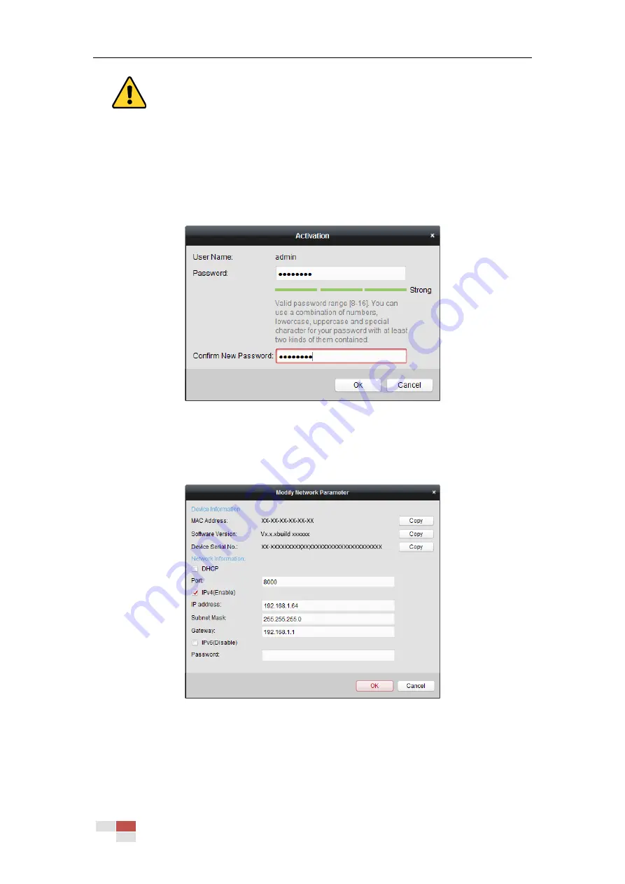
Figure 2-8


Activation Interface 

6.


Click OK to start activation. 

7.


Click Modify Netinfo to pop up the Network Parameter Modification interface, as shown in 

Figure 2-9. 


Figure 2-9


Modifying the Network Parameters 

8.


Change the device IP address to the same subnet with your computer by either modifying 

the IP address manually or checking the Enable DHCP checkbox. 

9.


Input the password to activate your IP address modification. 

Summary of Contents for DS-2DE4425W-DE3

Page 1: ...Network Speed Dome User Manual UD09562B...

Page 2: ...ous jurisdictions Other trademarks and logos mentioned below are the properties of their respective owners Legal Disclaimer TO THE MAXIMUM EXTENT PERMITTED BY APPLICABLE LAW THE PRODUCT DESCRIBED WITH...

Page 3: ...Hikvision IN THE EVENT OF ANY CONFLICTS BETWEEN THIS MANUAL AND THE APPLICABLE LAW THE LATER PREVAILS 0505061080411...

Page 4: ...must accept any interference received including interference that may cause undesired operation EU Conformity Statement This product and if applicable the supplied accessories too are marked with CE...

Page 5: ...eiling the device should be firmly fixed To reduce the risk of fire or electrical shock do not expose the indoor used product to rain or moisture This installation should be made by a qualified servic...

Page 6: ...accumulation good ventilation is required for a proper operating environment While shipping the product should be packed in its original packing Use the provided glove when open up the product cover...

Page 7: ...1 POWER UP ACTION 16 4 2 CONFIGURING LOCAL PARAMETERS 16 4 3 LIVE VIEW PAGE 17 4 4 STARTING LIVE VIEW 18 4 5 OPERATING PTZ CONTROL 20 4 5 1 PTZ Control Panel 21 4 5 2 Auxiliary Functions 22 4 5 3 Set...

Page 8: ...k 65 5 4 6 Configuring Scheduled Tasks 66 5 4 7 Clearing PTZ Configurations 67 5 4 8 Configuring Smart Tracking 68 5 4 9 Prioritize PTZ 69 5 4 10 Position Settings 69 5 4 11 Rapid Focus 70 CHAPTER 6 C...

Page 9: ...Hikvision SADP SOFTWARE INTRODUCTION 113...

Page 10: ...tion The presets can be added modified deleted and called Label Display The on screen label of the preset title azimuth elevation zoom time and camera name can be displayed on the monitor The displays...

Page 11: ...ackground where the light is strong Wide Dynamic Range WDR The wide dynamic range WDR function helps the camera provide clear images even under back light circumstances When there are both very bright...

Page 12: ...rs are allowed to access and control the same network camera via network simultaneously 3D Digital Noise Reduction Comparing with the general 2D digital noise reduction the 3D digital noise reduction...

Page 13: ...over the LAN If you want to set the network camera via a WAN Wide Area Network refer to Section 2 2 Setting the Network Camera over the WAN 2 1 Setting the Network Camera over the LAN Purpose To view...

Page 14: ...address into the address bar of the web browser and click Enter to enter the activation interface The default IP address of the camera is 192 168 1 64 Figure 2 3 Activation Interface Web 3 Create a p...

Page 15: ...list and select an inactive device Select inactive device Input and confirm password Figure 2 4 SADP Interface The SADP software supports activating the camera in batch Refer to the user manual of SAD...

Page 16: ...ress manually or checking the Enable DHCP checkbox Figure 2 5 Modify the IP Address 6 Input the password and click Modify to activate your IP address modification The batch IP address modification is...

Page 17: ...ement interface as shown in Figure 2 7 Figure 2 7 Device Management Interface 3 Check the device status from the device list and select an inactive device 4 Click Activate to pop up the Activation int...

Page 18: ...ecurity of your product Proper configuration of all passwords and other security settings is the responsibility of the installer and or end user Figure 2 8 Activation Interface 6 Click OK to start act...

Page 19: ...twork camera via a router Steps 1 Connect the network camera to the router 2 Assign a LAN IP address the subnet mask and the gateway Refer to Section 2 1 2 for detailed IP address configuration of the...

Page 20: ...of your own choosing using a minimum of 8 characters including upper case letters lower case letters numbers and special characters in order to increase the security of your product Proper configurati...

Page 21: ...der E g DynDns com Follow the steps below for normal domain name resolution and private domain name resolution to solve the problem Normal Domain Name Resolution Steps 1 Apply a domain name from a dom...

Page 22: ...op right of login interface 5 Input the user name and password and click The admin user should configure the device accounts and user operator permissions properly Delete the unnecessary accounts and...

Page 23: ...he live video and manage the camera with the client software Follow the installation prompts to install the client software and WinPcap The configuration interface and live view interface of client so...

Page 24: ...are contact technical support of our branch for camera firmware For detailed information about client software of our company refer to the user manual of the software This manual mainly introduces acc...

Page 25: ...ding the model address communication version and other will be displayed on screen for 40 seconds 4 2 Configuring Local Parameters The local configuration refers to the parameters of the live view and...

Page 26: ...et the saving path for the manually recorded video files Save downloaded files to Set the saving path for the downloaded video files in interface Picture and Clip Settings Set the saving paths of the...

Page 27: ...lick to logout the system Live View Window Display the live video Toolbar Operations on the live view page e g live view capture record audio on off regional exposure regional focus etc PTZ Control Pa...

Page 28: ...ecording Mute audio on and adjust volume Start stop digital zoom Enable disable regional exposure Enable disable regional focus Double click on the live video to switch the current live view into full...

Page 29: ...he on the toolbar to enter the regional exposure operation mode and the icon turns into Then drag the mouse to draw a rectangle on the image as the desired exposure region Click the on the toolbar to...

Page 30: ...e zoom iris focus buttons to realize lens control Figure 4 4 PTZ Control Panel Table 4 2 Descriptions of PTZ Control Panel Button Name Description PTZ Control Panel Hold and press the direction button...

Page 31: ...nd one touch park Speed Adjustment Adjust speed of pan tilt movements Preset Refer to 4 5 3 for detailed information of setting preset Patrol Refer to 4 5 4 for detailed information of setting patrol...

Page 32: ...ive view interface 2 Operate the 3D positioning function Click a position of the live video The corresponding position will be moved to the center of the live video Hold down the left mouse button and...

Page 33: ...Tilt the camera up or down Zoom in or out Refocus the lens 3 Click to finish the setting of the current preset 4 Edit a preset name by double clicking on the default name such as preset 1 The pre def...

Page 34: ...ial position 93 Set limit stops manually 35 Call patrol 1 94 Remote reboot 36 Call patrol 2 95 Call OSD menu 37 Call patrol 3 96 Stop a scan 38 Call patrol 4 97 Start random scan 39 Day mode IR cut fi...

Page 35: ...er from the list and click 3 Click to enter the adding interface of preset as shown in Figure 4 9 Figure 4 9 Adding Presets 4 Configure the preset number patrol time and patrol speed Name Description...

Page 36: ...the camera moves as the patrol path 8 automatically Steps 1 Set preset No 1 to No 32 Refer to 4 5 3 Setting Calling a Preset for detailed information of setting preset 2 Call preset No 45 and the came...

Page 37: ...ure 4 12 Patterns Settings Interface 3 Click to enable recording the panning tilting and zooming actions 4 Use the PTZ control buttons to move the lens to the desired position after the information of...

Page 38: ...limit stops and auto flip will be invalid and the 3D positioning operation is not supported 4 6 Playback Purpose This section explains how to view the video files stored in the network disks or memor...

Page 39: ...Audio on and adjust volume Mute Speed down Download Speed up Playback by frame Enable Disable digital zoom You can choose the file paths locally for downloaded playback video files and pictures in Loc...

Page 40: ...p up menu is shown in Figure 4 19 2 Set the start time and end time Click Search The corresponding video files are listed on the left Figure 4 19 Video Downloading interface 3 Check the checkbox in fr...

Page 41: ...terface 2 Select the file type of capturing the pictures from the list as timing alarm motion etc 3 Set the start time and end time Click Search The corresponding picture files will be listed 4 Check...

Page 42: ...ra manual recording and scheduled recording In this section you can follow the instructions to configure the scheduled recording By default the record files of scheduled recording are stored in the me...

Page 43: ...ction and the HDD is full the new record files overwrite the oldest record files automatically The Pre record and Post record parameters vary depending on different camera models 4 Click OK to save th...

Page 44: ...select to record by event the video will be recorded when any of the events is triggered 6 Click to save the settings 5 1 2 Configuring Capture Schedule Purpose You can configure the scheduled snapsh...

Page 45: ...e You can follow below configuration instructions to upload the snapshots to FTP Upload continuous snapshots to FTP Steps 1 Configure the FTP settings and check Upload Picture checkbox in FTP Settings...

Page 46: ...User Manual for creating the file path For your privacy and to better protect your system against security risks we strongly recommend the use of strong passwords for all functions and network devices...

Page 47: ...disk 3 When the initialization completed the status of disk will become Normal as shown in Figure 5 7 Figure 5 7 View Disk Status Define the Quota for Record and Pictures 1 Input the quota percentage...

Page 48: ...he functions vary depending on different camera models 5 2 1 Configuring Motion Detection Purpose Motion detection is a feature which can trigger alarm actions and actions of recording videos when the...

Page 49: ...n Settings Normal Steps 1 Click and drag the mouse on the live video image to draw a motion detection area 2 Click to finish drawing You can click to clear all of the areas 3 Move the slider to set th...

Page 50: ...ght switch Auto Switch Switch the day and night mode according to the illumination automatically Scheduled Switch Switch to the day mode and the night mode according to the configured time You need to...

Page 51: ...end time of the arming task 3 After you set the scheduled task you can click and copy the task to other days optional Figure 5 12 Arming Time Schedule 4 After setting the arming schedule you can click...

Page 52: ...nkage method Figure 5 14 Linkage Method Check the checkbox to select the linkage method Notify Surveillance Center Send Email Upload to FTP Memory NAS Trigger Alarm Output and Trigger Recording are se...

Page 53: ...event occurs refer to Section 5 2 4 Configuring Alarm Output to set the alarm output parameters Trigger Recording Record a video when an event occurs You have to set the recording schedule to realize...

Page 54: ...for motion detection Refer to Section 5 2 1 Configuring Motion Detection 6 Click tab to select the linkage method taken for tampering notify surveillance center send email and trigger alarm output ar...

Page 55: ...ring Motion Detection 5 Click tab to select the linkage method taken for alarm input including Notify Surveillance Center Send Email Upload to FTP Memory Card NAS Trigger Alarm Output and Trigger Reco...

Page 56: ...a name in for the alarm output optional 4 The Delay time can be set to 5sec 10sec 30sec 1min 2min 5min 10min or Manual The delay time refers to the time duration that the alarm output remains in effe...

Page 57: ...xception The exception type can be HDD full HDD error network disconnected IP address conflicted and illegal login to the cameras Steps 1 Enter the Exception settings interface Configuration Event Bas...

Page 58: ...functions vary depending on different camera models 5 3 1 Detecting Audio Exception Purpose When you enable this function and audio exception occurs the alarm actions will be triggered Steps 1 Enter...

Page 59: ...ccording to the actual environment 4 Check the checkbox of Sudden Decrease of Sound Intensity Detection checkbox to enable the sudden drop detection Sensitivity Range 1 100 the smaller the value the m...

Page 60: ...gger the alarm when the sensitivity is high a very small object can trigger the alarm 5 Click tab to enter the arming schedule setting interface The time schedule configuration is the same as the sett...

Page 61: ...to draw a rectangle on the image as a defense region 3 Click on the image to specify a corner of the rectangle and right click the mouse after four corners are configured 6 Configure the parameters f...

Page 62: ...the linkage method taken for intrusion detection Notify Surveillance Center Send Email Upload to FTP Memory Card NAS Trigger Alarm Output and Trigger Recording are selectable Refer to Section 5 2 1 Co...

Page 63: ...trigger the alarm when the sensitivity is high a very small object can trigger the alarm Detection Target You can select human vehicle or all human vehicle as the detection target from the dropdown li...

Page 64: ...2 1 Configuring Motion Detection 9 Click to save the settings 5 3 5 Configuring Region Entrance Detection Note The function varied depending on different speed domes Purpose Region entrance detection...

Page 65: ...etection You can select human vehicle or all human vehicle as the detection target from the dropdown list If Human is selected only human beings will be identified as detection objects and as well as...

Page 66: ...You can click the button to clear all pre defined regions 7 Set sensitivity level Sensitivity level ranges from 1 to 100 The value of the sensitivity defines the size of the object which can trigger...

Page 67: ...is triggered Steps 1 Enter the Unattended Baggage Detection settings interface Configuration Event Smart Event Unattended Baggage Detection 2 Check the checkbox of Enable to enable the Unattended Bag...

Page 68: ...upload to FTP trigger channel smart tracking and trigger alarm output are selectable Refer to Section 5 2 1 Configuring Motion Detection 11 Click button to save the settings 5 3 8 Object Removal Detec...

Page 69: ...ction 10 Click tab to select the linkage method taken for the object removal alarm Notify surveillance center send email upload to FTP trigger channel smart tracking and trigger alarm output are selec...

Page 70: ...ensure the surveillance efficiency It can also reduce the use of bandwidth in a digital network system Preset freezing function is invalid when you calling a pattern Preset Speed You can set the spee...

Page 71: ...anning and tilting as 2 seconds 5 seconds 10 seconds NC Normally Closed or NO Normally Open Preset Status Set the preset name display duration while calling the preset as 2 seconds 5 seconds 10 second...

Page 72: ...Stops When you set these two limit types at the same time Manual Stops is valid and Scan Stops is invalid 3 Click the PTZ control buttons to find the left right up down limit stops you can also call t...

Page 73: ...can click to delete the initial position and restore the factory default initial position 5 4 4 Configuring Park Actions Purpose This feature allows the camera to start a predefined park action scan...

Page 74: ...Patrol Pattern or Preset as Action Type you need to select Action Type ID from the dropdown list 6 Click to save the settings 5 4 5 Configuring Privacy Mask Purpose Privacy mask enables you to cover...

Page 75: ...will be listed in the Privacy Mask List area set the value of Active Zoom Ratio on your demand and then the mask will only appear when the zoom ratio is greater than the predefined value Figure 5 32 P...

Page 76: ...ime and end time of the recording task 6 After you set the scheduled task you can click and copy the task to other days optional Figure 5 34 Edit the Schedule and Task Type 7 Click to save the setting...

Page 77: ...Tracking settings interface Configuration PTZ Smart Tracking Figure 5 36 Configure Smart Tracking 2 Check the Enable Smart Tracking check box to enable smart tracking function 3 Set zoom ratio for tra...

Page 78: ...ecks the color of the detected target several times during tracking and compares the color resemblance to determine whether it should continue to track the target or not If the returned resemblance is...

Page 79: ...speed dome turns back to the north direction 4 You can manually set GPS information including longitude and latitude 5 Click to save the settings 5 4 11 Rapid Focus Purpose Rapid focus is a function t...

Page 80: ...above steps to add other scenes b Adjust calibration line i Select an added scene A red line displays on live image ii Adjust the length and position of the line by dragging its two endpoints Note The...

Page 81: ...P IP Settings Purpose TCP IP settings must be properly configured before you operate the camera over network IPv4 and IPv6 are both supported Steps 1 Enter TCP IP settings interface Configuration Netw...

Page 82: ...The router must support the route advertisement function if you select Route Advertisement as the IPv6 mode Configuring DDNS Settings Purpose If your camera is set to use PPPoE as its default network...

Page 83: ...the settings Figure 6 3 DynDNS Settings NO IP Steps 1 Enter Server Address of NO IP 2 In the Domain text field enter the domain name obtained from the NO IP website 3 Enter the Port of NO IP server 4...

Page 84: ...sibility of the installer and or end user 4 Click to save and exit the interface Configuring Port Settings Purpose If there is a router and you want to access the camera through Wide Area Network WAN...

Page 85: ...router 3 Set the port mapping mode To port mapping with the default port numbers Choose To port mapping with the customized port numbers Choose And you can customize the value of the port number by y...

Page 86: ...ox Enable SNMP v1 Enable SNMP v2c Enable SNMP v3 to enable the feature 3 Configure the SNMP settings The configuration of the SNMP software should be the same as the settings you configure here 4 Clic...

Page 87: ...ething of your own choosing using a minimum of 8 characters including upper case letters lower case letters numbers and special characters in order to increase the security of your product Proper conf...

Page 88: ...load the captured pictures to FTP server you also have to enable the continuous snapshot or event triggered snapshot in Snapshot interface Configuring Email Settings Purpose The system can be configur...

Page 89: ...ched pictures Authentication optional If your email server requires authentication check this checkbox to use authentication to log in to this server and enter the login user name and password For you...

Page 90: ...Or you can check the Custom checkbox on the right and input a desired server address 5 Click to save the settings Hik Connect is an application for mobile devices With the App you can view live image...

Page 91: ...ter the country host name IP validity and other information 4 Click OK to save the settings OPTION 2 Start the installation when signed certificate is available 1 Select Signed certificate is availabl...

Page 92: ...r 443 the format of the URL is https IP address port number eg https 192 168 1 64 81 Configuring QoS Settings Purpose QoS Quality of Service can help solve the network delay and network congestion by...

Page 93: ...h The switch forwards the identity and password to the authentication server RADIUS server The switch forwards the certificate of authentication server to the network camera If all the information is...

Page 94: ...ttings 6 After the configuration connect the camera to the protected network Integration Protocol Purpose If you need to access to the camera through the third party platform you can enable Hikvision...

Page 95: ...le the function 4 Click Add to add a new ONVIF user Set the user name and password and confirm the password You can set the user as media user operator and administrator 5 Click Modify to modify the i...

Page 96: ...ct the stream type to video stream or video audio composite stream The audio signal will be recorded only when the Video Type is Video Audio Resolution Select the resolution of the video output Bitrat...

Page 97: ...ost scenes H 265 H 265 function varies depending on different speed dome models You need to reboot the camera if you want to turn on or turn off the H 264 H 265 If you switch from H 264 to H 265 direc...

Page 98: ...is the better the audio quality will be Input Volume Slid the bar to turn up down the volume The value ranges from 0 to 100 Environmental Noise Filter Select ON or OFF in the dropdown list to enable o...

Page 99: ...kbox to enable the Fixed Region function 2 Select a stream type You can set the ROI function for main stream sub stream or third stream 3 Click and then drag the mouse to draw a red frame in the live...

Page 100: ...ng line crossing intrusion etc 6 3 Configuring Image Settings On the event configuration page click to show the PTZ control panel or click to hide it Click the direction buttons to control the pan til...

Page 101: ...rity and Manual Auto The iris shutter and gain values will be adjusted automatically according to the brightness of the environment You can limit the changing ranges of iris and shutter in Auto mode f...

Page 102: ...exposure condition It lengthens the shutter time to ensure full exposure Slow Shutter Level When slow shutter is set as ON you can select the slow shutter level from the dropdown list The slow shutter...

Page 103: ...dome Auto In Auto mode the day mode and night mode can switch automatically according to the light condition of environment The switching sensitivity can be set to 1 2 3 Figure 6 28 Auto Mode Sensiti...

Page 104: ...mera identify and suppress the strong light sources that usually flare across a scene This makes it possible to see the detail of the image that would normally be hidden White Balance The White Balanc...

Page 105: ...6 32 3D Digital Noise Reduction If you are a professional technician you can set it to Expert Mode then adjust Space DNR Level and Time DNR Level The level ranges from 0 to 100 Figure 6 33 Expert Mode...

Page 106: ...ialization Zoom Limit You can set Zoom Limit value to limit the maximum value of zooming The value can be selected from the list Local Output You can select the output mode to ON or OFF Note These fun...

Page 107: ...the text overlay Steps 1 Enter the Text Overlay settings interface Configuration Image OSD Settings 2 Check the checkbox in front of textbox to enable the on screen display 3 Input the characters in...

Page 108: ...Image Image Parameters Switch 2 Check the checkbox of Link to Preset or Scheduled Switch to enable the function Only one function can be enabled in the same time 3 When you enable the function of Link...

Page 109: ...arm Input Number of Alarm Output and Firmware Version Property are displayed The information cannot be changed in this menu It is the reference for maintenance or modification in future Figure 6 41 De...

Page 110: ...43 Time Sync by NTP Server You can click to make sure that the NTP server is connected If the camera is connected to a public network you should use a NTP server that has a time synchronization functi...

Page 111: ...the Time Zone in which the camera locates Figure 6 45 Time Zone Settings Configuring DST Daylight Saving Time Purpose Daylight Saving Time DST is a way of making better use of the natural daylight by...

Page 112: ...mputer through the network RS 232 function varies depending on different speed dome models Steps 1 Enter RS 232 Port setting interface Configuration Advanced Configuration System RS 232 Figure 6 47 RS...

Page 113: ...nse you can check Open Source Software Licenses 6 4 2 Maintenance Upgrade Maintenance Rebooting the Camera Steps 1 Enter the Maintenance interface 2 Configuration System Maintenance Upgrade Maintenanc...

Page 114: ...ation file You need to reboot the camera after importing configuration file Upgrading the System Steps 1 Enter the Maintenance interface Configuration System Maintenance Upgrade Maintenance 2 Select F...

Page 115: ...iles will be displayed on the Log interface 4 To export the log files click Save Log to save the log files in your computer System Service Steps 1 Enter the interface of configuring the remote connect...

Page 116: ...Authentication type from the dropdown list Digest and digest basic are selectable 3 Click to save the settings Configuring IP Address Filter Purpose With this function on the camera allows certain IP...

Page 117: ...ying Delete an IP Address Left click an IP address from filter list and click Delete Delete all IP Addresses Click Clear to delete all the IP addresses 5 Click to save the settings Configure Security...

Page 118: ...ly recommend the use of strong passwords for all functions and network devices The password should be something of your own choosing Using a minimum of 8 characters including at least three of the fol...

Page 119: ...re 6 56 Add a User Modify a User Steps 1 Left click to select the user from the list and click 2 Modify the User Name Level or Password 3 In the Basic Permission field and Camera Configuration field y...

Page 120: ...elete a User Steps 1 Left click the user name you want to delete and click 2 Click on the pop up dialogue box to delete the user Online Users Enter the Online Users configuration interface Configurati...

Page 121: ...ine Users You can see the current users who are visiting the device through this interface User information such as user name level IP address and operation time is displayed in the User List Click Re...

Page 122: ...line devices every 15 seconds from the subnet where your computer locates It displays the total number and information of the searched devices in the Online Devices interface Device information includ...

Page 123: ...umber 3 Enter the password of the admin account of the device in the Password field and click to save the changes For your privacy and to better protect your system against security risks we strongly...

Page 124: ...Hikvision Figure A 1 2 Modify Network Parameters...

Page 125: ......

Reviews: