HIKVISION DS-2CE12DF3T-PIRXOS User Manual Download Page 6


Make sure the wall is strong enough to withstand 
three times the weight of the camera and the mount. 


If the product does not function properly, contact 
your dealer or the nearest service center. DO NOT 
disassemble the camera for repair or maintenance by 
yourself. 

2.1


Installation of Type I Camera 

2.1.1


Ceiling/Wall Mounting Without Junction Box 

Before you start: 
Ceiling mounting and wall mounting are similar. 
Following steps take ceiling mounting as an example. 
Steps: 
1.


Paste the drill template (supplied) to the place 
where you want to install the camera. 

2.


(Optional) For cement ceiling, drill the screw holes 
with a 5.5 mm drill and insert the supplied wall 
plugs. 

3.


(Optional) Drill the cable hole, when the cables are 

routed through the ceiling. 
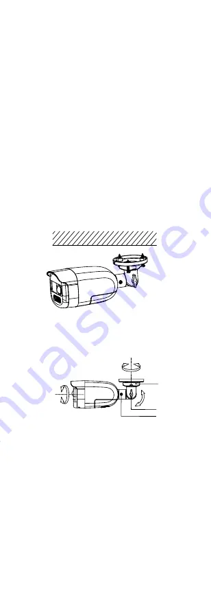
4.


Align the screw holes in the bracket to the ceiling, 

and secure the camera with three PA4 × 25 screws 
(supplied). 


Figure 2-1


Secure Camera to Ceiling 

5.


Connect the power cord and video cable. 

6.


Power on the camera to adjust the view angle 

according to the figure below. 

Rotation Position 

[0° to 360°]

Tilt Position

[0° to 180°]

Pan Position

[0° to 360°]

Trim Ring


Figure 2-2


3-Axis Adjustment 

1).


Loosen the trim ring to adjust the pan position 
[0° to 360°]. 

2).


Loosen screw 

 to adjust the tilt position [0° to 

180°]. 

3).


Loosen screw 

 to adjust the rotation position 

[0° to 360°]. 

7.


Tighten the screws to lock the positions. 

2.1.2


Ceiling/Wall Mounting with Junction Box 

Before you start: 


You need to purchase a junction box in advance. 


Ceiling mounting and wall mounting are similar. 
Following steps take wall mounting as an example. 

Steps: 
1.


Paste the drill template for junction box to the place 
where you want to install the camera. 

Summary of Contents for DS-2CE12DF3T-PIRXOS

Page 1: ...es to the models below Type Model Type I Camera DS 2CE12DF3T PIRXOS Type II Camera DS 2CE72DF3T PIRXOS This manual may contain several technical mistakes or printing errors and the content is subject...

Page 2: ...CIAL CONSEQUENTIAL INCIDENTAL OR INDIRECT DAMAGES INCLUDING AMONG OTHERS DAMAGES FOR LOSS OF BUSINESS PROFITS BUSINESS INTERRUPTION OR LOSS OF DATA CORRUPTION OF SYSTEMS OR LOSS OF DOCUMENTATION WHETH...

Page 3: ...t any interference received including interference that may cause undesired operation EU Conformity Statement This product and if applicable the supplied accessories too are marked with CE and comply...

Page 4: ...dapter to avoid over heating or a fire hazard caused by overload Make sure that the plug is firmly connected to the power socket Make sure that the device is firmly fixed if wall mounting or ceiling m...

Page 5: ...detection Built in speaker Three predefined audio files and one custom audio file are available 1 2 Overview 1 2 1 Overview of Type I Camera PIR Lens Microphone Siren Main Body Bracket Power Cord Vid...

Page 6: ...ted through the ceiling 4 Align the screw holes in the bracket to the ceiling and secure the camera with three PA4 25 screws supplied Figure 2 1 Secure Camera to Ceiling 5 Connect the power cord and v...

Page 7: ...25 screws supplied Figure 2 4 Secure Junction Box on Wall 7 Route the cables through the bottom cable hole or side cable hole of the junction box and connect the cables 8 Fix the junction box cover o...

Page 8: ...the mounting base and secure it Figure 2 9 Install Camera Back 7 Connect the corresponding cables such as power cord and video cable 8 Power on the camera to adjust the view angle according to the fig...

Page 9: ...2 12 Secure Mounting Base on Junction Box s Cover 5 Route the cables and use four PM4 screws to combine the junction box s cover with its body 6 Repeat the step 7 to 8 of 2 2 1 Ceiling Mounting Witho...

Page 10: ...ll the menu Note The actual display may vary with your camera model Steps 1 Connect the camera with the TVI DVR and the monitor as shown in figure 3 1 Camera TVI DVR Monitor Figure 3 1 Connection 2 Po...

Page 11: ...MAGE MODE MOTION DET PRIVACY ANTI BANDING SMART LIGHT LIGHT BACK EXIT SAVE EXIT THRESHOLD LEVEL SLOW SHUTTER AUDIO SETTINGS BACK EXIT SAVE EXIT AUDIO VOLUME MODE ALARM SETTINGS Figure 3 2 Main Menu Ov...

Page 12: ...s simultaneously in the field of view WDR balances the brightness level of the whole image and provides clear detailed images HLS Highlight Suppression It is the same visual effect as the solar eclips...

Page 13: ...shades of red blue color of the image WHITE BALANCE MODE R GAIN B GAIN BACK EXIT SAVE EXIT MANUAL 5 5 Figure 3 4 WHITE BALANCE BRIGHTNESS Brightness refers to the brightness of the image You can set t...

Page 14: ...more sensitive the device is to dark environment LEVEL You can adjust the maximum brightness of supplement light MODE The function is to reduce frame rate in low light environment in order to increase...

Page 15: ...nes in a camera s view where motion is to be detected PRIVACY This function allows you to block or mask certain area of a scene to protect personal privacy from being recorded or live viewed You can t...

Reviews: