background image

8

English

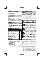
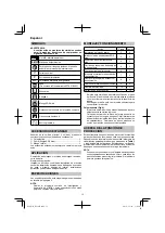
STANDARD ACCESSORIES

In addition to the main unit (1 unit), the package contains the 

accessories listed in the below.

  Plastic Case .................................................................1

  Bull Point (SDS-max shank) .........................................1

  Side Handle ..................................................................1

Standard accessories are subject to change without notice.

APPLICATIONS

Demolishing concrete, chiseling o

  concrete, grooving, bar 

cutting.

Application examples:

Installation of piping and wiring, sanitary facility installation, 

machinery installation, water supply and drainage work, 

interior jobs, harbor facilities and other civil engineering 

works.

SPECIFICATIONS

The speci

fi

 cations of this machine are listed in the Table on 

page 5.

NOTE

  Due to HiKOKI’s continuing program of research and 

development, the speci

fi

 cations herein are subject to 

change without prior notice.

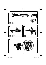
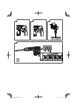
MOUNTING AND OPERATION

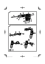
Action

Figure

Page

Installing the side handle

2

2

Inserting SDS-max tools

3

3

Removing SDS-max tools

4

3

Deciding working position of tool

5

3

Switch operation

6

3

Locking-on the On / O

  switch

7

4

Releasing the On / O

  switch

8

4

How to use the demolition hammer*

9

4

Speed change

10

4

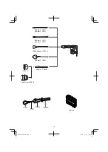
Selecting accessories

18

*  Operate this Demolition Hammer by utilizing its empty 

weight. The performance will not be better even if it is 

pressed or thrust forcibly against the work surface.


Hold this Demolition Hammer with a force just su

  cient 

to counteract the reaction.

Warming up (Fig. 9)

  The grease lubrication system in this unit may require 

warming up in cold regions.

  Position the end of the bit so makes contact with the 

concrete, turn on the switch and perform the warming 

up operation. Make sure that a hitting sound is produced 

and then use the unit.

ABOUT THE PROTECTION 

FUNCTION

This tool has a built-in protection circuit for preventing 

damage to the unit in the event of an abnormality. Depending 

on the nature of the abnormality, the display lamp will 

fl

 ash 

as shown in 

Table 1

 and the unit will cease to operate. In 

such cases, verify the problem indicated by the 

fl

 ashing and 

take whatever steps are necessary to correct the problem.

NOTE


Repair may be required if the display lamp continues to 

fl

 ash after taking all necessary steps to correct the problem. 

If the problem persists, please arrange for repairs.

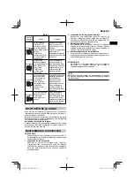
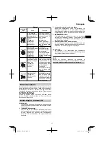
Table 1

Display 

lamp 

fl

 ashing

Cause

Solution

Flash

Internal temperature 

has risen beyond 

the unit’s speci

fi

 ed 

temperature.

(Temperature 

increase protection 

function)

Turn o

  the unit 

and allow it to cool 

down for about 15 to 

30 minutes.

When the temperature 

goes down, press the 

impact rate selector 

switch to recover.

Flash

Excessive pressure 

applied to the tool 

has resulted in an 

overload.

(Overload 

protection function)

Press the impact rate 

selector switch to 

recover. Try to avoid 

tasks that will apply 

excess pressure to 

the unit.

Flash

Tool is connected 

to a power source 

whose voltage is 

too high.

(Circuit protection 

function)

Connect the unit to a 

power supply matching 

the input voltage 

speci

fi

 ed on the 

nameplate. Press the 

impact rate selector 

switch to recover.

Flash

Sensor signal read 

error.

(Control monitoring 

function)

Press the impact rate 

selector switch to 

recover. Repair may 

be required if this error 

continuously occurs.

GREASE REPLACEMENT

This Demolition Hammer is of full air-tight construction to 

protect against dust and to prevent lubricant leakage.

Therefore, this Demolition Hammer can be used without 

lubrication for long periods. Replace the grease as described 

below.

Grease Replacement Period

After purchase, replace grease after every 6 months of 

usage. Ask for grease replacement at the nearest authorized 

Service Center.

MAINTENANCE AND INSPECTION

CAUTION

  Be sure to switch OFF and disconnect the attachment 

plug from the receptacle to avoid a serious accident.

1. Inspecting accessories

  Since use of a dull accessory, such as a bull point, a 

cutter, etc. will degrade e

  ciency and cause possible 

motor malfunction, sharpen or replace with a new one as 

soon as abrasion is noted.

000Book̲H41ME.indb   8

000Book̲H41ME.indb   8

2019/12/18   13:42:44

2019/12/18   13:42:44

Summary of Contents for H 41ME

Page 1: ...H 41ME Handling instructions Instrucciones de manejo Instruções de uso en es pt en es pt 000Book H41ME indb 1 000Book H41ME indb 1 2019 12 18 13 42 39 2019 12 18 13 42 39 ...

Page 2: ...2 1 2 000Book H41ME indb 2 000Book H41ME indb 2 2019 12 18 13 42 40 2019 12 18 13 42 40 ...

Page 3: ...3 3 4 5 6 000Book H41ME indb 3 000Book H41ME indb 3 2019 12 18 13 42 42 2019 12 18 13 42 42 ...

Page 4: ...4 7 8 9 10 L H Bpm 1500 2000 2500 2870 000Book H41ME indb 4 000Book H41ME indb 4 2019 12 18 13 42 43 2019 12 18 13 42 43 ...

Page 5: ...5 H41ME V 110 V 120 V 127 V 220 V 230 V 240 V P 1050 W Bpm 1500 2870 min 1 min kg 5 0 kg 000Book H41ME indb 5 000Book H41ME indb 5 2019 12 18 13 42 43 2019 12 18 13 42 43 ...

Page 6: ...Keep children and infirm persons away When not in use tools should be stored out of reach of children and infirm persons GENERAL POWER TOOL SAFETY WARNINGS WARNING Read all safety warnings and all instructions Failure to follow the warnings and instructions may result in electric shock fire and or serious injury Save all warnings and instructions for future reference The term power tool in the war...

Page 7: ... and persons below 8 Wear protective shoes to protect your feet 9 Wear a dust mask Do not inhale the harmful dusts generated in chiseling operation The dust can endanger the health of yourself and bystanders 10 Mounting the tool To prevent accidents make sure to turn the switch off and disconnect the plug from the receptacle When using tools such as bull points cutters etc make sure to use the genu...

Page 8: ...te In such cases verify the problem indicated by the flashing and take whatever steps are necessary to correct the problem NOTE Repair may be required if the display lamp continues to flash after taking all necessary steps to correct the problem If the problem persists please arrange for repairs Table 1 Display lamp flashing Cause Solution Flash Internal temperature has risen beyond the unit s spe...

Page 9: ...not become damaged and or wet with oil or water 4 Replacing supply cord If the replacement of the supply cord is necessary this has to be done by the manufacturer of this agent in order to avoid a safety hazard CAUTION In the operation and maintenance of power tools the safety regulations and standards prescribed in each country must be observed NOTE Due to HiKOKI s continuing program of research ...

Page 10: ...tas eléctricas que no se utilicen fuera del alcance de los niños y no permita que utilicen las herramientas eléctricas personas no familiarizadas con las mismas o con estas instrucciones Las herramientas eléctricas son peligrosas si son utilizadas por usuarios sin formación ADVERTENCIAS DE SEGURIDAD GENERAL DE LA HERRAMIENTA ELÉCTRICA ADVERTENCIA Lea todas las instrucciones y advertencias de segur...

Page 11: ...ición OFF Si el enchufe se conecta a una toma de corriente mientras el interruptor principal se encuentra en la posición ON la herramienta eléctrica se pondrá en marcha inmediatamente y podría provocar un accidente grave 3 Si la zona en la que va a efectuarse el trabajo se encuentra alejada de la fuente de corriente utilice un cable prolongador del grosor suficiente y que tenga la capacidad nomina...

Page 12: ...s SDS max 4 3 Decisión de la posición de trabajo de la herramienta 5 3 Funcionamiento del interruptor 6 3 Bloquear el interruptor de activación desactivación 7 4 Liberar el interruptor de activación desactivación 8 4 Cómo usar el martillo de demolición 9 4 Cambio de velocidad 10 4 Selección de los accesorios 18 Emplee este martillo de demolición utilizando el peso del mismo El rendimiento no mejor...

Page 13: ...prolongados Cambie la grasa como se describe a continuación Periodo de sustitución de la grasa Después de su compra cambie la grasa después de cada 6 meses de uso Solicite la sustitución de la grasa al centro de servicio técnico más próximo MANTENIMIENTO E INSPECCIÓN PRECAUCIÓN Asegúrese de colocar el interruptor en la posición OFF y de desenchufar el enchufe de la toma de corriente para evitar ac...

Page 14: ...xperientes e Efetue a manutenção de ferramentas elétricas Verifique a existência de desalinhamentos ou curvaturas das peças móveis rupturas de peças e quaisquer outras condições que possam afetar o funcionamento das ferramentas elétricas ADVERTÊNCIAS GERAIS DE SEGURANÇA PARA A FERRAMENTA ELÉTRICA ADVERTÊNCIA Leia todas as instruções e advertências de segurança Deixar de seguir as instruções e as a...

Page 15: ... o interruptor na posição de ligado ON a ferramenta elétrica começará a funcionar imediatamente podendo provocar um grave acidente 3 Quando o local de trabalho não possuir uma fonte de energia utilize um cabo de extensão de espessura e de potência nominal suficientes A extensão deve ser mantida o mais curta possível 4 Não toque na broca durante ou logo após a operação A broca fica muito quente dur...

Page 16: ...E OPERAÇÃO Ação Figura Página Instalação do cabo lateral 2 2 Inserção das ferramentas SDS max 3 3 Remoção das ferramentas SDS max 4 3 Decisão da posição de trabalho da ferramenta 5 3 Operação do interruptor 6 3 Travamento do interruptor de Ligar Desligar 7 4 Destravamento do interruptor de Ligar Desligar 8 4 Como usar o martelo 9 4 Mudança da velocidade 10 4 Seleção dos acessórios 18 Opere este Ma...

Page 17: ...rita abaixo Período de troca da graxa Depois da compra troque a graxa a cada seis meses de uso Solicite a troca da graxa ao Centro de Serviço Autorizado mais próximo MANUTENÇÃO E INSPEÇÃO PRECAUÇÃO Certifique se de desligar a ferramenta e de desconectar o cabo de alimentação da tomada elétrica para evitar um acidente grave 1 Inspeção dos acessórios Como o uso de um acessório desafiado como uma pon...

Page 18: ... 313472 280 mm 313473 400 mm 313474 W50 400mm 313475 L 150 mm 313478 313477 400 mm 313476 200 mm 313479 L 373792 373245 331247 373244 330209 000Book H41ME indb 18 000Book H41ME indb 18 2019 12 18 13 42 46 2019 12 18 13 42 46 ...

Page 19: ...19 000Book H41ME indb 19 000Book H41ME indb 19 2019 12 18 13 42 47 2019 12 18 13 42 47 ...

Page 20: ...ty Tower A 15 1 Konan 2 chome Minato ku Tokyo 108 6020 Japan Distribuido por Calle Isaac Newton No 286 2do Piso Col Polanco V Sección Del Miguel Hidalgo C P 11560 Ciudad de México México 000Book H41ME indb 20 000Book H41ME indb 20 2019 12 18 13 42 47 2019 12 18 13 42 47 ...
Reviews: