5
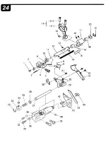
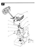
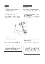
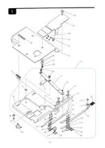
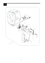
下切刀座的安装方法
:
注意
在调整刀片时,务必将电源开关关掉之后,
请专门的技术人员进行操作
1.
固定座
1
的端面到固定刀
2
的端面之间的
距离为
167mm
的位置处。
固定刀刀刃至弹簧片
3
顶端的距离为
0.3mm
2.
固定杆
4
的顶点与活动刀
5
刀尖之间的
距离为
163.5mm
,并请固定杆与活动刀平
行时安装。
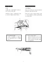
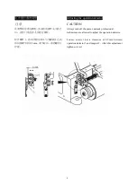
● 将切刀的前端往箭头的方向稍微旋转,则
其剪切的效果会更好。
Lower knife seat installation
CAUTION
Always turn off the power, and ask professional
technicians are allowed to adjust the lower knife.
1. The position should be at distance of 167mm
which is from holder 1 to the fixed knife 2.
The distance between fixed knife blade to the top
spring plate 3 is 0.3mm.
2. Distance from fixed lever 4 vertex to activities
knife 5 knifepoint is 163.5mm. And please install
when the fixed lever and activities knife is in
parallel .
z
Turn the cutter’s front a little as the arrow
shows, then the cat linr would be better.
Summary of Contents for HW762T
Page 1: ......
Page 25: ... 8 J 2 21 11 12 20 19 5 4 18 17 ...
Page 27: ...II 10 3 11 7 1 23 ...
Page 31: ...II 6 18 14 17 10 JO 11 I 10 32 31 I I I I I I 25 26 I I 28 4 29 23 35 34 33 8 I f 21 36 ...
Page 33: ...17 ...
Page 35: ... 5 4 1 id 23 24 a 17 18 19 1 ...
Page 37: ... 2 1 4 3 10 11 15 I 13 14 ...
Page 39: ...ar 9 1 0 12 14 b 6 ll n 15 1 15 15 2 7 5 24 ...
Page 41: ... 8 4 3 21 40 3 54 51 53 46 53 49 50 47 ...
Page 44: ......
Page 48: ...14 13 11 10 7 5 4 2 1 ...
Page 50: ...2 7 3 y 1 4 12 ...
Page 52: ...24 4 7 1 27 2 20 30 20 31 20 36 26 37 ...
Page 54: ...r 31 25 26 p f 27 I f ___ 22 21 i 20 32 33 12 10 11 10 8 3 13 1 9 ...
Page 56: ...13 t 14 t t 1r _ 11 15 20 24 ...
Page 58: ...5 ...
Page 60: ... 2 I 1 10 12 11 9 i 19 18 17 15 13 ...
Page 62: ...1 8 3 9 10 ...
Page 64: ... 0 7 1 33 11 34 v _10 vg 17 13 21 I 16 2 3 4 5 1 5 2 5 32 31 ...
Page 66: ...2 ...
Page 68: ...fl ...
Page 70: ...fB t ...
Page 72: ...26 25 1 2 4 22 27 38 35 34 6 19 2 19 19 1 20 21 J 14 29 44 43 41 40 ...
Page 74: ......
Page 76: ...2 3 4 5 6 22 7 8 18 10 11 14 13 ...
Page 78: ......
Page 92: ...34 33 31 1 4 23 9 8 2 13 12 29 20 11 ...
Page 94: ...22 21 ...
Page 96: ... 1 13 ...
Page 98: ... 1 15 ...
Page 100: ...1 25 21 20 19 3 18 10 17 13 16 15 17 ...
Page 102: ... 1 3 11 19 ...
Page 111: ...7 36 3 2 2 专用型接线端子图 包缝 含第三光眼功能 ...
Page 112: ...8 36 3 2 3 专用型接线端子图 细嘴 ...
Page 128: ...24 36 3 2 2 Special terminal connectiondiagram overlock with the third sensor function ...
Page 129: ...25 36 3 2 3 Special terminal connection diagram cylinder bed overlock ...

