background image

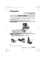
Summary of Contents for SFX-33

Page 1: ... standard Main scanning density 8 pels Sub scanning density 3 85 lines mm Standard mode 7 7 lines mm Fine mode 15 4 lines mm Super fine mode Compression mode MH Modified Huff man and Sanyo original Reading method CIS Contact image sensor Recording method Thermal printing Power supply AC 120V 50 60Hz Power consumption Stand by 5W Transmission 20W Reception 130W Copy 150W Overall dimensions 381 W x ...

Page 2: ...xplanation 36 7 PRINTING OF THE REPORT AND LISTS 4O 44 7 1 Activity report 40 7 2 One touch and Speed dial list 40 7 3 Transmission report 41 7 4 Feature switch list 41 7 5 RAM CODE List 42 8 FLOW CHART OF AUTO RECEPTION MODE 45 47 1 Auto reception with FAX TEL switchover function isON 45 2 Auto reception with FAX TEL switchover function is OFF 46 3 Answer reception mode 47 L 9 BLOCK DIAGRAM AND S...

Page 3: ...et Keep the SFX 33 away from water If water accidentally enters the unit unplug the AC power cord immediately DO NOT PLUG THE UNIT IN AGAIN Contact and authorized Sanyo service center or dealer Handling precaution Avoid bending kinking or damaging the power cord Never insert or remove the power cord with wet hands Also be sure to hold the cord by the plug when removing it from the outlet Do not re...

Page 4: ...dial line is switch No 00 to Push button telephone 1 1 Rotary dialing telephone 14 SET MODE I l TIME SET 13 FEATURE SW I If you are still not sure which dialing system your telephone line is using contact your telephone company To change dialing mode to PULSE 1 Press MENU 4 times 2 Press SET L 3 Press MENU twice 4 Press SET1 5 Press SET 6 Enter 0 and 1 to select the PULSE mode 7 Press SET1 8 Press...

Page 5: ...ll automatically Inserl the end of the roll into the recording paper exit slot Open button Use only the recording paper specified for the SFX 33 High grade thermal paper The SFX 33 is compatible with the high grade thermal paper a new type of fax recording paper with plain paper quality Unlike regular thermal paper the high grade thermal paper does not fade with time can be written on with pencil ...

Page 6: ... D DATA 6 Press SET or MENU SET Initialize O T S D DATA and goes to next item REPORT DATA MENU Not initialize O T S D DATA just goes to next item REPORT DATA 7 Press SETl or MENU SETl Initialize REPORT DATA and goes to next item RAM CODE SET MENU Not initialize REPORT DATA just goes to next item RAM CODE SET 2 RAM CODE SET IRAM CODE CLEAR I 10 T S D CL EAR I lREPORT DATA CLR I 2 RAM CODE SET 8 Pre...

Page 7: ...ABCDE STATION TEL No 19 l 222 333 4444 8 Press SET to complete The display shows next setting item FEATURE SWITCH 3 FEATURE SW Your station name and fax number Header can be printed either outside the document or inside the document You can select the desired setting using feature switch No 20 Default setting is printed outside of the document Printing outside of the original Jun 26 9512 00 ABC 1 ...

Page 8: ...has a separate cursor Selecting a character L 1 Use number key 5 to select the desired character group The first line of the selected group appears each time the number key 5 is pressed 2 Use number keys 2 or 8 to scroll up or down the display 3 Use number keys 4 or 6 to move the cursor 2 over the desired character 4 Press one touch key 7 to enter the selected character into registration area The ...

Page 9: ...acters EDWARD ABCDE 6 Press SET 7 Enter the fax or telephone number 8 9 A maximum of 32 digits can be entered including pauses and hyphens Example 1 222 3333 Press SET To program other one touch numbers repeat steps 3 8 above Press STOP C to finish one touch number programming l 222 3333 I I O T No I Jun 26 95 12 00 _ For instructions on printing out a numerical list of programmed named and number...

Page 10: ...teps 3 8 to program other numbers 9 Press STOP C to finish speed dial number programming 1 222 3333H I S D No In I Jun 26 95 12 00 QFor instructions on printing out a list of programmed names and numbers To interrupt programming press STOP C To enter a hyphen between a number press SPEED DIAL c To enter a three second pause between two digits of a number press REDIAL P in the appropriate place A s...

Page 11: ... Repeat steps 3 9 to change other one touch dialing speed dialing numbers 10 Press STOP C to finish changing Canceling programmed one touch speed dialing numbers 1 Press MENU 3 times 2 Press SET 3 Press the one touch dialing key or speed dialing number of the number you want to cancel Example One touch dialing number 2 to cancel 4 Press SET 5 Press MENU 6 Press SET Repeat steps 3 6 to cancel other...

Page 12: ...entered using 24 hour system The month day and year should be entered as 2 digits each Example to enter June 26 1995 12 00 press 0 6 2 6 9 5 1 2 0 and 0 5 Press SET 6 Press STOP C to finish calendar clock setting 6 26 95 12 00 12 STAT10N coDE I lJun 26 95 12 001 If you make a mistake move the cursor to the appropriate place then enter the correct number Press to move the cursor right Press to move...

Page 13: ...ment feed roller 2 press the document sensor as shown in the figure 3 Clean the document feed roller 2 then dry it thoroughly to prevent the document from jamming Docu Document sensor 2 3 Cleaning the document feed roller 1 If the document jamming or overlapping frequently occurs clean the document feed roller 1 with a cotton swab dampened with a small amount of a neutral detergent 1 Open the oper...

Page 14: ...Recording paper cover Open button I Origina Itray guide Operation panel l iml OFF M H w M LINE Telephone line jack Original slot Monitor volume control Ringer volume control EEL Inner view Extension telephone jack ent sensor older t release P e t fee Green release lever 14 ...

Page 15: ... when the unit is set to ANSWER mode 9 SPEED DIAL key Press this key when using speed dial O REDIAUP key Press this key to redial the last number dialed Press this key to insert a pause between two digits in a number being dialed 11 Number keys O 9 These keys are used to dial fax and phone numbers and to change various functions 12 ONE key Press this key to switch from pulse dialing to Touch Tone ...

Page 16: ...ctive thickness 1 original sheet multi sheets thickness 0 05 0 15 mm 0 08 0 13 mm per sheet 0 002 0 006 0 003 0 005 Notes on the suitability of documents Allow ink and or glue to dry completely before inserting a document Do not transmit curled or folded documents Make sure that any paper clips staples or pins have been removed from documents When an original is carbon paper waxed paper or vinyl c...

Page 17: ...rward scanning by CIS The 2nd sensor works for detecting the separation of the document and controls paper feeding for stop position 4 2 Reception Mechanism As shown in Fig 4 1 the recording paper is pressed by the platen roller and the thermal head The platen roller is rotated by the reception motor and feeds the recording paper forward When printing is finished the recording paper is fed to the ...

Page 18: ... data from image signal processor to line memory from line memory to MODEM thermal head and CODEC Real time clock 0 Stepping motor control 1 0 ports for Mechanism Operation Panel LCD control signal 1 2 Gate Array LPD65622 1 0 port for NCU and TEL control signal 1 3 512Kbit EP ROM contains CPU control 1 4 64Kbit SRAM This is used for temporary memory for image data memory and various data memory su...

Page 19: ...smission mechanism control This PCB contains driving circuit for Tx stepping motor and sensor circuit for original document M 7 PCB Power supply This is a switching LCD display This contains 16x 9 Thermal head power supply and outputs 5V 12V and 24V 1 line LCD with segment and common driver circuit This contains 1728 dots 8 dot mm of heat generating elements and their driver circuit 10 Contact Ima...

Page 20: ...CIS 3 Adjust the pressure repositioning ClS See page 30 Out of document area is reproduced Dirt on the platen roller roller 2 Clean the platen roller See page 13 as blurred black When copying white verlical line 1 Stains on the thermal head 1 Clean the thermal head appears on the reproduced copy See page 30 2 Heating elements of the thermal 2 Replace the thermal head head opens See page 30 LCD sho...

Page 21: ...ssible from the operation panel Check the same as described 1 1 I i YES NO Check the connection of CN2 M 1 Check the Main PCB M 1 I YES I Check the operation panel PCB M 2 I 3 LCD indicates CHECK PAPER ROLL Is recording paper set properly I t YES Is the Receiving cover closed securely I Check the connection of CN5 M 1 YES NO Is PAP CN5 pin No 4 less than 0 5V Check the reception mecha PCB M 5 I I ...

Page 22: ...sion motor 5 No copy is made NO Is the Head test OK See page 34 Check the printing circuit I a Printing Circuit To be confirmed by the Head test see page 34 I Check the connection of CN4 M 1 and CNTPH Thermal head t YES NO Does 24V ap Check the power supply PCB M 7 1 L I YES NO Does HVON CN7 pin No 1 work properly High at printing YES NO Do the signals DATA CN4 pin No 3 CLK CN4 pin No 4 appear nor...

Page 23: ...S Check the M 1 PCB 6 Can notenter the TxJRx mode by pressing STARTl switch under OFF HOOK condition a In case of the extension telephone connected to the SFX 33 Check the connection of extension telephone and MJ42 M 4 YES NO Is HS CN31 pin No 8 low on the NCU PCB M 3 Check the NCU M 3 I Check the M 1 PCB b In case of the Built in telephone I Check the connection of CN31 M 3 and CN3 M 1 I 4 OK Che...

Page 24: ...a below a Tone dial Does TXLINE CN31 pin No 17 on M 1 NO appear normal i YES Do TELI and TEL2 FC33 pin No 7 and 8 NO appear normal Check M 1 MAIN PCB t YES I I I Check M 4 TEL PCB i b DP dial Does the DP signal CN31 pin No 11 on M 3 appear NO normal Check M 1 MAIN PCB 1 Do TEL1 and TEL2 FC33 pin No 7 and 8 NO appear normal Check M 3 NCU PCB Check M 4 TEL PCB I ...

Page 25: ...7 vSTART NO L NO IS 24V output w YES IS F701 Blow Off k YES IS Q701 short Es LX GiEl w IS ZD701 703 YES short NO I 1 YES IS D703 short NO 4 IS D705 707 k YES short YES1 k Q704 short NO 1 NO e r wh Restart after exchanging 25 ...

Page 26: ... No recording paper 24 Recording paper jam R 25 Cutter locks R E30 E33 Image deficiency CODE CONTENTS CLASSIFICATION 30 Exceed the error line limitation R I I t 31 RTN transmission R I 32 I RTN reception IT L I 33 I over5seconds per line I R E40 E41 Error in the other party Transmission is interrupted caused by pressing the STOP key I Paper remains in the cutter position SYMPTOM and NOTES These er...

Page 27: ... it is possible that the other party disconnected the line by some reasons Although MCF signal to respond MPS or CFR signal was transmitted no carrier signal received within 6 seconds Q EOP MPS EOP General terms E60 E62 Incomplete transmissions due to deficient line CODE CONTENTS CLASSIFICATION SYMPTOM and NOTES 60 Fall down Out T Training failure even with fall down to 2400 bps 62 Continuous 300 ...

Page 28: ...8Z 9 m KJd u 1 IN EK3d r13N C M Illi il ritl 11 un p qu apall 6u AIC3WJ iil Jnclas sMt3J3s OM n 9 ml h z 9 ad 914 c z 1 Qlp J ...

Page 29: ... securing the M 2 Operation Panel PCB Fig 6 7 Remove LCD by removing two screws Fig 6 7 9 Removal of M 5 Rx Mechanical Control PCB a Remove the receiving mechanical unit Refer to the 6 l 3 b Remove two screws securing the M 5 Rx mechanical control PCB Fig 6 8 c Disconnect the connectors CN51 CN52 CN53 and CN54 Fig 6 8 10 Removal of M 6 Tx Mechanical Control PCB a Remove the transmission mechanical...

Page 30: ...receiving mechanical unit Refer to the 6 1 3 b Remove one screw securing the cutter unit Fig 6 14 c Disconnect the connector of the cutter unit d Remove three screws securing the guide cutter three pieces from the cutter unit Fig 6 15 Please note that one wire fixer is fixed together with screw When re assembling put it to the same position 4 Replacement of the ADF Automatic Document Feeder unit a...

Page 31: ...l INITIAL SET SET Initial Set Press MENU v 2 RAM CODE SET SET Changing RAM CODE Press MENU COPY Print RAM CODE LIST w 13 SCAN TEST SETI Scanning Test I I Press MENU v 4 MODEM TEST SET SET 1 Press MENU Modem check Thermal head check 6 PANEL TEST SET Operation Panel check Press MENU v 7 SELF CHECK SET Self diagnostic for the circuitry Press MENU 31 ...

Page 32: ...U Goes to next test mode RAM CODE SET 7 In case of S RAM error Alarm sounds continuously and the machine goes into dead lock condition Repairing is required Check S RAM and Peripheral circuit b RAM CODE SEITING 1 Press SET MENU Refer to 6 3 l 2 Press MENU over 1sec 3 Press SET or COPY 4 5 6 7 SET Change the contents COPY Issue RAM CODE LIST Input the SW No using numeric or MENU key to select SW No...

Page 33: ... START to call for the next signal Press COPY to call for the previous signal I 9600 BPS 0 SIGNAL ORDER 9600 BPS 0 7200 BPS 0 4800 BPS 0 2400 BPS 300 BPS 0 1 21OOHZ 1100Hz PB8 NO SIGNAL RETURN TO 9600BPS 0 The signals of 9600 7200 4800 2400 and 300 BPS can be changed its carrier frequency and pattern as shown below Press Rx MODE to change its pattern at each stage 0 1850Hz continuously 1 1650Hz co...

Page 34: ...Press MENU 5 times or just press 6 3 Press SET 1 Press SETl MENU over 1sec Refer to 6 3 1 2 Press MENU 6 times or just press 7 I1 INITIAL sET I 15 HEAD TEST I 11 INITIAL SET I 16 PANEL TEST I II LCD LED BUZZER I The whole LCD and all LED will be turned over and 2 times of the beeping tone will be heard 4 Press keys according to the guidance of display All keys on the panel will be displayed in seq...

Page 35: ...ignal generated on test purpose Check the operation of STBON STBINT and the connection Data Transfer Check the connection of INT2 IN CASE OF ERROR 1 MODEM CHECK MODEM CLOCK NG MODEM 300B NG MODEM 9600B NG MODEM DREQ NG MODEM DREQW NG MODEM 11OOH NG 2 MUSIP CHECK MUS I P SHWDT NG MUSI P INTR NG 3 RTC CHECK RTC lSEC NG 4 TPH l F CHECK TPH T21NT NG TPH WIDTH NG TPH UDMA NG No clock detection possible...

Page 36: ...ce No melody GREEN SLEEVE No Tel Fax switchover Number of rings that sounds before the SFX 33 switches from telephone mode to fax reception mode when a manual fax transmission or voice call is received in the AUTO mode 03 10 Hold melody 00 01 This is to set the melody released to the telephone line when the conversation is put on hold 01 Key operation sound 00 01 02 OFF ON IOW ON high CIN outside ...

Page 37: ...nnection ON or OFF 57 FAX TEL parallel connection 00 OFF 01 ON 00 SW No 60 93 are only for service engineer SW No Setting items Communication mode Setting No Contents AUTO G3 Fact set 00 Exdanation This RAM SW fixes the communication mode md is normally set on AUTO 60 00 01 OFF ON 00 START is effective without lifting the handse hen the setting is ON SETTING No 01 Jsed for hooking up 2 facsimiles ...

Page 38: ... 0 sec 05 2 5 sec 06 3 0 sec 06 1 0 5 sec step 12 6 0 sec 75 Transmission start 00 2400BPS This is to set the training start speed of the speed 01 4800BPS MODEM 02 7200 BPS It is recommended that if Tx error occurs 03 9600BPS 03 frequently set to 4800BPS 76 TSI 01 Transmit in This is to set the condition of transmitting TSI anycase 02 Transmit only 02 when CSI receives 77 DCS timing 00 Response to...

Page 39: ...oaded cable between fax and 02 3 6 Km exchange station Set in response to the 03 5 6 Km distance to the exchange 88 Closed network 00 OFF 00 Even when closed network communication is communication Free 01 ON set Rx is free from any SANYO fax machines pass SANYO unit at ON SETTING No 01 93 Paper precut 00 OFF 00 In case of ON SFX 33 precut the recording 01 ON paper along the fold for reception and ...

Page 40: ...Jun 26 9 013 2 B7 WFl m 2 Jun 26 la OO U 55 EB 3 1 m RECU No 139TE STfIRT TIME FI IRTNER Pf IGE RESLli_T E W8X 3 4mr8E 1 Jun 26 9 31zi g ccc 1 I IK 2 Jun 26 10 30 13 44 rJmI 1 IOK 2 One touch and Speed dial list 1 Press MENU 3 times 2 Press COPY Sample of one touch speed dial list 3 0 T S D SET I O T S D LIST I CINETCIUCH SPEED DIRL LIST Xt4n 26 95 2z LZ L3 No P9RT r S N9ME NIJM13ER ONETOUCH D19L ...

Page 41: ... l TIME SET 3 Press MENU twice 3 FEATURE Sw 4 Press COPY FEATURE SW LIST Sample of feature switch list U S A NCI 001 011 061 071 081 091 101 171 201 261 271 281 311 361 501 541 571 FEFITURE J L I ST T s 95 1 2 GJQ SWITCH NfiME D I RL MODE PFIL SE TIME tlITO RED I F L No OF RINGS REMOTE Rx F T SW CIUER MELODY KEY SOUND HERDER PRINT CLDSED Rx RESOLUT 10N CONTRRST Tx REPORT HRLFTONE ZOOM COPY IWTO PR...

Page 42: ...13 3sec IZ121 2 TIMES 05 5 TIMES 33 33 03 ON 7 TIMES IZI1 GREENSLEEUES E12 HIGH Dl ON OUTSIDE E13 OFF E131 NOT RETURN 03 NOT RETURN 001 OFF EII P9TTERN2 al ON al ON Da OFF EIB OFF INITIW_ SET EKO TONE B3 3SQC E121 2 TIMES E15 5 TIMES C331 33 03 ON 7 TIMES EIl GREENSLEEUES E12 HIGH IZI1 ON OUTSIDE W OFF 133 NOT RETURN 0Z131 NOT RETURN 1 OFF all PRTTERN2 EIl ON 031 ON EuZI OFF ZIEII OFF 7 5 RAMCODEL...

Page 43: ...IOM COPY al ON al ON 541 FIUTO PROG Dll ON CDll ON 571 P17RRLLEL TEL DEI OFF CDB OFF WI COM MCIDE BE WJTO DDI f4JT0 611 MNL HOOK UP EIEII OFF OFF 621 SPEED DISP EIUI OFF E3E31OFF 631 G3 MONITOR EI131 OFF lZiEl IJFF 661 CED CHECK E131 45 5sec CZi3j 45 5sec 671 Rx SPEED CEIl 96Ev3BPS El EIDBPS 681 CED FRQ EIgl 21EIDHz OEII 21L3EIHz 691 TCF INTERUfIL CEEl 5rns l15ms 13Ell 5ms l15ms 7DI FSK CHECK C ZI...

Page 44: ...l ON 541 FIJTO PROG EI1 ON EII ON 561 DISTINCT RNG EIEI OFF EIEII OFF 571 Pi RLLEL TEL EI l OFF E OFF 6Eil COM MODE EiOl fWITO W F7UT0 611 MNL HOOK UP EIt31 OFF EIEI OFF 621 SPEED DISP EIIZ OFF EIIZI OFF 631 G3 MONITOR OZI l OFF EIEO OFF 661 CED CHECK w131 45 5sec 031 45 5s c 671 Rx SPEED 1 96 BPS gl 96EWIBPS 681 CED FRGL CEIEII 21 ZIHz 12EII 21WIHZ 691 TCF INTERUf7L E 5nls l15ms EIEO 5ms l15ms 7E...

Page 45: ... switchover function is ON Incoming call 1 Y N Y N I Capture the line I CNG detect mode Check CNG during 2 5sec Y N Y I N Operator call and CNG detect RAM SW 09 1 Y t N EXT TEL handset is connected to the line 1 Send FAX signal Y A Reception Y N Return to Stand by 45 ...

Page 46: ... 2 Auto reception with FAX TEL switchover function is OFF Incoming call I Y N t I EXT TEL handset is connected to the line Capture the line Send FAX signal N ...

Page 47: ...reception mode Check TAS start until incoming ring signals are counted during 40 seconds Y N N Y CNG detection and No signal detection N N Y b Send FAX signal N t Reception End TAS operation Y Return to stand by ...

Page 48: ..._ ____l G P 1 0 I II I II Ml MAIN I II II NCU iNTERFACE II l ____ ____ _l MECHANICAL I DOCUMENT 1 CONTROL 1 1 GPIIO PAPER SENSOR I v_ I RECEIVING M5 I STEPPING KEY TDISPLAY STEPPING MOTOR MOTOR CONTROL MOTOR DRIVER CONTROL ERATION GPIIO I 1 PANEL 1 1 II I I THERMAL THERMAL THERMAL PAPER HEAD I HEAD I CONTROL 1 Ml NGINFISI I I FAX ED _ _ I I IN al SPEAKER E H NDES o M3 NCU _ _ _ _ _ _ _ _ _ _ __ 1 ...

Page 49: ...ne is encoded modulated through the NCU b Reception 1 The signals received from the line enter the MODEM through the NCU 2 In the same manner as in transmission the coded data which is demodulated by the MODEM is stored into the FIFO as one byte data with an interruption signal requested by the MODEM 3 The CPU reads out and decodes each one bit of the data from the FIFO and outputs to the thermal ...

Page 50: ...ol Block IC701 pulse wide modulation PWM Over current limitation OCP Stabilize the output 24V and protect against electric hazards 5 AC DC Converter Block Secondary D704 Rectificating diode 3 pin type L703 Smoothing choke coil C720 Smoothing capacitor 6 Comparator Block Q704 Comparative transistor ZD704 Reference Voltage 506V VR701 Variable resistor adjust the 24V 7 DC DC Converter Block VIN 24V _...

Page 51: ... I R701 I BY C707 b C705 C703 r 51 ...

Page 52: ...m Iv 3 2 LINE ETEL m 7 r m 84 Ik 4 a r l I M3 NCU GP65 I f t44 TEL GP661 r Ml MAIN GP63 r I M6 TX MECI A CONTROL GP6e I I M2 OPERATION PANEL L LCD DISPLAY 16X1 J n w ...

Page 53: ... C5 i 1 CS2 c SLLMji Ll L 3 FE4Z21OO1 31I 1 00 ICNA 2 5v ICN 1 CN llS ICN4 16 I 5 6 m l F JP5 IISE b 7 A I 1 dP9 m RAMr5 JP3 m AMCS A VnAMCs 3 30 5 sc IP7 t I IP1O q e LC3B64PML I 7 Vcc L VRTC G2B L 4 7 I I _ lC1 v 7TC VCc 2 2A I R R91 lK 56 92K 2A 17W14 3 70 3 7s 5 6C L _l 1Cec S 7A ...

Page 54: ...NTOF OLLER H__ HIM SPEED UOMA PO T3 On u CONTUOLLEF4 TrxJ TO1 T02 T03 cs OACTO OACT1 wOTCUT 1NT7 1NT3 1NT4 1NT5 INT6 TIO T12 I TXM MOTORS I B TI14f5Fl CHO TIMEil CH1 PORTS B TIMER C H2 TIMER CH3 U i i CXO _ T D 330K OAKEN 4 00 SKI EEEl I 7 hr vOO PIN 12 23 33 40 56 774m0 51ai VCc oo GNO Pm vss 70 83 10s 114 i27 133 149 Vcc s4 171 ...

Page 55: ...c 7 TP lPHS S1 56K 7 m7 IAG Vcc HEAT 56K C63 XTAL3 27P 20 736M L LKOUT ce4 u 12P LKIN z 09QMCK Q oml b3T APoMOK AGCS MUTE J 1 71 P 7 YECKO 3 V c T BLM3 I 4 00 1 c3FlE4z2io 3i641 00 AvOD OATA PRCCESIM WIT TMERM L E AO CONTP OL M o D E M lNTFI 2 7C JP13 L4 3e4zzAo 31a7i TXM CIS PH12B it NS 3 1 JP12 as PHI CLSP I L 15s1 TPEN2 TPEN3 TPEN4 TPuCLK TPHJ T TPWRO TF LAT m ICN6 9 1 2 7C1 I 1C8 B EZ 3C l l 5...

Page 56: ...Ml Main P W B 4 6 L i L I 1 0 1 u I m I ...

Page 57: ...s ccP TC 53K 77 IP1lNC AWL I m t lcs 1 4C 24 A 19 1 OM 0 2 LCO Pa 7 PBS Pa P 3 PB Pmo 17AS S6KX4 FIA6 2i 0KX4 Vcc P d I HE Vcc 1 FI107 6 50 J6K r4x blON 7 7 47 77 7 7 PAZ 41 AO I t 1 al 1 I L 75 T 76 I 1 1 I PCS PC5 Pc 4 PC2 nxM Pcl I r I p 5 3 RE4Z 1OO 64 Vcc 6LM31 C1ll I 1 I 1 1 1 c cm u ICN5 2 CL ICNS i 11111111 Ri16 1 2K TTTTTTTT A 0 5v vcc N c 1 V W TRSN 4 ...

Page 58: ...Ml Main P W B 6 6 I I n I u I m 1 ...

Page 59: ...Panel P W B d l mu i U H OIL L r 1 1 1 AK 2 K 1 Ka K 2 K r 7 7 g il _ ____ ____ _ l_ ___ ___ _ _ ___ _ r 1 1 J 1 T 0 3 0 iii 0 J U 3 m lo m 0 co u l N I Ir 0 u I m I 59 ...

Page 60: ... c 1 1 lBO 2W 3UE4L29000090 I 11 l _ _J C306 112 2 100 NC IFC33 6 I II Fc301 L2 IFC33 7 W4io lp301 c30e R30S __T P_5 _ 2 2 1 21 O 47u 250 METAL INTEL ll 1 L 1 4N1 lP30a 22 1 2 s vR30 SV3SS c309 INC IFCS3 3 I II w PS 250S I 52 H 32 1 k XTELi IFc J3 4 2 0 1 4 EXTEL lP 3 20 rF XTEL2 I C33 5 C317 Rx LINE lCN31 16j ER UIID M P 0304 C340 2 c 3 _ C3402 ...

Page 61: ...ER F1408 NC FF Hs 6 180K I eu Ro RI 5 cdi3 1000 040 i MC34012 lM FI L 4 7U5 4A6 C409 95 7U C41O 0 047u 50v S1ZB40 MJ43 2 IMIC Md43 3 1 M 143 1 l i P M J43 4 lSP N t wTE Ic N4i 6 I 3RE4L1300i79i X 2 L409 F ZD40 i GZalOY L40S C414 47000 s0 GZzy ooav L407 C41 OU 2 V L409 u 3RE4Li300 79 X Z H R7 i 0Hs1cN4i 11 1C403 _ C422 1 MIC 2 7 3 4i6 C420 0 033u 2SV TX1 MS 47u 25v 67000 50 II R4 is R416 220 C417 3...

Page 62: ...M4 Telephone P W B CANADA 1 z u z n n m a x________ I r 0 I u t m I ...

Page 63: ...R I Z050 i I Mvn ICF152 3 RX MOTOR Y rN 1C301 1 8 LILN2Q03A 1 1 L 24V 1 R303 3 6 I L 2N5 i 1 I 24V 1 Rsoe e sx Z0502 2 4X 4 7K CUTEFl UNIT CN51 3 l C lT I 1 1 1 1 I t J7 1 I ___________________ 1 0 24 1501 24V 1 0 P OZe 16C Vcc TM03 lcN62 1 GNO 1C601 1 1 C603 1 47 6 3 1 v1OEO CN63 1 GNO CN63 2 GNO CP163 7 c l 2 C 61 2 5 L GL D Cr la i i LED I 1 Leo i cN6i 61 24v CP461 171 24 ...

Page 64: ...POLYESTEL F 7 bin R707 3RE4L21OO14OO T014001 C711 T70i 0704 2 2 250 SAQ9 M 02 2 R LA in 7 ERB44 04v1 II 0702 l l i i 0701 2SK1101 ZD701 q r 7 2 30 G o 1 J701 C713 R709 co 0 1 2W 1702 5 0703 Ena9i 02 C708 4700 I 11C1770 1000 a 220HM C7 0 F 1000 35 II 1 1 G 4706 aEEE3 MC3 t166T 341i67T 1C702 C N71 2 1 24 N7i 3 l i2V I 25 CN71 5 5V 1 N7 4 12 I 726 g so N71 6 IG D N7L 7 1s 0 1 ...

Page 65: ... 1 I n It b 1 44 C145447 I 1 L _ m ___ a Ja 01 i id r 1 we 1 1 1 m U w m R108 RICIb JP1l AK dIili2 1 I J JJil r F y j i n Cbl n57 7W14 k ...

Page 66: ...Ml P W B B side n J L5 n D m 2 WI N 1 N m 0 JP16 E JP17 JP 18 n JP13 OJP12 1 t C29 C28 3RE4B13006650 B o 66 ...

Page 67: ...M2 P W B 67 ...

Page 68: ...M3 P W B L k S w 68 ...

Page 69: ...1 69 ...

Page 70: ......

Page 71: ...M6 P W B 71 ...

Page 72: ...M7 P W B A o J e 72 ...

Page 73: ...HZ44 Dial tone Busy tone detection U S A not use CN3 CN31 Detect High IHS External TEL hook up detection CN3 CN31 HOOL UP LOW PCE1 Ringing signal detection CN3 CN31 Detection AC signal EARTH Circuit earth signal U S A not use CN3 CN31 ON High DP Dial pulse signal CN3 CN31 ON High CML Connect modem to line signal CN3 CN31 ON High RXLINE Reception signal CN3 CN31 Analog signal TXLINE Transmission si...

Page 74: ...CN61 CN63 CIS VIDEO Video image signal CN6 CN61 Analog signal CN63 CIS s1 Document stock detection CN6 CN61 ON LOW s2 Document read position detection CN6 CN61 ON LOW s3 Document size detection CN6 CN61 ON LOW TMIO 3 Transmission motor pulse signal CN6 CN61 TMOO 3 Transmission motor drive signal CN62 TX MOTOR HVON Thermal head power ON signal CN7 CN71 ON High HGND Thermal head power GND CN7 CN71 S...

Page 75: ...NT4 1NT5 1NT6 TIO T12 TOO T02 RSTIN SPCLK INT PDMCK PI MDT PDMDT Vss C3 C4 C5 MUTE EYECKO VDD TPHPHS DIAG TPHLAT TPHDRQ TPHDAT TPHC1 K Vss TPEN4 TPEN3 TPEN2 TPEN1 HtA rPOWER AD 1 AD 1 VSS AD2 AI 3 AD4 AD 5 VDD ADE AD 1 ALC AL1 CLKOUT Vs CLKIN VDD AL2 AL3 AL4 TOP VIEW TC35165F CLK VDD INM1 L TEST4 TEST3 TEST2 B 0 TEST1 Vss Z AVDD VC L AIN1 AMON A1N2 IMAGE T PRC3CESSUR AddressDataBus 1 System Block ...

Page 76: ...E3 TPE4 INTo DTCK DI INT1 TPHC CLKD GND TPH 1 CK1 M CK3M TESN TCLK CNTO N C NUCS NCS AO I 222223 333 33 33 3 3 4 567890 123 45 67 8 9 0 ULN2003A TC4053 D lY 1 16 VDD OY 2 15 Y COM lZ 3 14 X COM Z COM 4 13 lx Oz 5 12 ox INH 6 11 A VEE 7 10 B VSS 8 9C a STB4 STB1 i I RAMCS RAM3 RAM1 ROMCS ROM2 ROM1 1 pE4 TpE0 STBINT i t 20 736MHz TPHC 1 7W14 1A 3 t 2A GND TOP VIEW I Vcc IY 3A 2Y TC4053BPIBF X COMMON...

Page 77: ... MC34014 In E Ml T VD Diode Bridge I HS I HI I Ht 2 iF n m I 4 Tone I Frequency Divider RG BLOCK DIAGRAM MC34012 mTX013 11 1 14 200K Lee l 57K OK RLC Q301 0 9V Transmit Re u ator 13 Amp 10K LC 12 I I I 7 VI I i Mute lj 9 logic Delay 10K i 5 VDD Regulator 9 600K J 100K 8 77 ...

Page 78: ...4 A9 A4 6 23 All A3 7 03 q 22 OE AZ 6 21 Alo rn A1 9 n 20 ml z AO 10 19 1 06 1 01 11 g 18 1 07 1 02 12 17 1 06 X K Top view AO A12 Address Input WE Read write control input OE Out put enable input CEI CE2 Chipenablelnput l 01 1 08 Data lflpUt out put VCC GND Power Ground pin Vcc DATA OUTPUTS 00 07 GND VPP 11111111 AO A15 ADDRESS INPUTS FY DECODER x a DECODER Block Diagram G 524 288 BIT CELL MATRIX...

Page 79: ... D CD 1 8 V02 FC2 2 7 Gnd FC1 3 6 VCC Vin 4 5 Vol TopView TC35123 VDD 1 16 RXINB VBIAS 2 15 J RXINA TXOUT 3 14 I VSS2 Vssl 4 13 J AGC5 MUTE 5 12 J AGC4 DPDMCK 6 11 J AGC3 DPDMDT 7 10 J APDMDT PD 8 9 3 APDMCK TOP VIEW MC34119 6 VCC I Vin 4 1 5 FC1 3 I r 50K 8 2 125K 2 FC2 50K Bais Circuit MC34119 7 TC35123 AAA g 54 Vol 52 CD F i5i l APDMDT APDMCK m 79 ...

Page 80: ...m 200V 706 707 10 0 5A Zener diode ZD701 702 GZA30X Vz 30V Pc 0 5W ZD703 DZB27C Vz 27V Pc lW ZD704 GZA5 6X Vz 5 6V Pc 0 5W ZD705 GZA5 1 x Vz 5 1 V Pc 0 5W ZD706 GZA4 7X Vz 4 7V Pc 0 5W Ic IC701 Ic FA531OP IC702 Down chopper MC34166T Vout 5V regulator control lout 3A Ic IC703 Voltage regulator TA78L012AP Vout 12V lout 150mA IC704 Voltage regulator TA79L012AP Vout 12V lout 150mA Photo Couier P701 TL...

Page 81: ...I I vIDEO NSS DCS TR TCF ET f 3 RJ T RTC EOP DCN 1 RECEPTION C AUTO AOUT RECEIVE RING TONE RING TONE DETECT LAMP CML REIAY NCU R DISP SEND SIGNAL n MCF RECEIVE VIDEO UI n SIGNAL RTC EOP DCN 2 TEL RESERVATION OTHERS 2 CALL UP AFTER SENDING D CALL UP FROM T SIDE HAND SET slOE I HOOKOFF CML RELAY NCU SEND SIGNAL 1 VIDEO RTC n n n PRI Q PRI Q PRI Q RECEIVE n SIGNAL PIPIPIN OPERATOR n CALL OPERATOR CAL...

Page 82: ... SW AUTO AUTO RECEIVE IET UP I DETECT ZINGING rONE o k VIDEO RTC fuPs cF TRA NING VIDEO DIS CONNECT D CHANGE MODE B VIDEO RTC Eo l NSS Dc5 TRA NING TCF cFR TRAINING E PHONE RESERVATION CALL UP FROM T SIDE T R HOOK OFF M VIDEO RTc PRI Q PRI Q PIP PIN 7 PRI Q SPEARK TALK OPERATOR CALL HOOK OFF F PHONE RESERVATION CALL UP FROM R SIDE T R M VIDEO RTC Q OPERATOR CALL H PIPIPIN HOOK OFF PRI Q m PIP PIN ...

Page 83: ...14 EXPLODED VIEW FIGURE A i 83 ...

Page 84: ...o 044 oB64 Q9 d 21 b N X3 627 T M 3 69 B71 A B2fJ FIGURE B 84 ...

Page 85: ... 0 El G fi 0 E2 FIGURE C 85 ...

Page 86: ...41 1 CANADA 4 6327354604 RATING LABEL LR64883 1 CANADA 5 6326643891 BRACKET EARTH 1 4110256104 SCR S TPG BIN 3X6 1 BRACKET BOTTOM 4111256707 SCR BIN 4X5 EARTH 1 4110461003 SCR PAN SW 4X6 2 PW AC CORD EARTH 4110060501 WASHER OUT TW 4 1 AC CORD EARTH 4110258104 SCR S TPG BIN 3X6 PW 2 4110256104 SCR S TPG BIN 3X6 MI PCB 2 4110256104 SCR S TPG BIN 3X6 NCU 1 Ref No I PART tie A6 A7 A8 A9 Al O B77 Al 1 ...

Page 87: ...AGE CIS 1 B69 6327306492 WIRE HARNESS 190MM IOP 1 CIS CN63 6322543409 LUG CIS CHASS ELC 2 B70 6326680933 PULSE MOTOR TX MOTOR 1 B71 6326668115 JUMPER LEAD 23P 115MM 1 CN6 CN61 A31 6327399209 AC CORD ASS Y 2500MM 1 A32 6327343367 JUMPER LEAD 315MM 28P 1 CN2 CN21 A33 6327308539 WIRE HARNESS 150MM 16P 1 CN7 CN71 A34 6327032809 LIQUID CRYSTAL DISPLAY 1 A35 6322496729 SPEAKER 160HM 1 A42 6326666096 SOC...

Page 88: ...GLAZE 22K JA 1 16W MT GLAZE 22K JA 1 16W MT GLAZE 22K JA l 16W MT GLAZE 10K JA l 16W MT GLAZE 47K JA l 16W MT GLAZE 56K JA 1116W MT GLAZE 56K JA l 16W MT GLAZE 56K JA l 16W MT GLAZE 56K JA l 16W my 3 3 1 1 2 1 1 1 1 2 4 8 1 2 1 1 2 1 1 1 2 2 2 2 2 2 3 3 2 2 1 1 4 1 1 1 4 4 1 1 1 1 2 1 1 1 1 2 1 2 2 2 1 1 2 2 2 1 1 1 2 2 1 1 1 1 1 1 1 1 1 1 2 1 2 1 1 1 2 2 1 1 Ref No PART FJo DESCRIPTION Q ty R104 ...

Page 89: ...W 1 R405 4010378104 MT GLAZE 150K JA l 10W 1 R404 4010379408 MT GLAZE 180K JA l 10W 1 R411 4010379408 MT GLAZE 180K JA IIIOW 1 F401 4240020903 FUSE 125V 0 25A CANADA 1 F402 4240020903 FUSE 125V 0 25A CANADA 1 Ref No PART No DESCRIPTION Q PC BOARD 5 B74 CN54 CN53 CN52 CN51 IC501 Q501 Q502 Q503 Q504 ZD501 ZD502 D501 D502 C503 R505 R502 R504 R506 R503 R508 B75 S2 SI CN62 CN63 CN61 IC601 ZD601 C603 R6...

Page 90: ...4W CARBON 12K JA l 4W PLUG 16P PLUG 2P HEAT SINK P Q701 HEAT SINK S D704 1C702 TERMINAL EARTH A H TERMINAL EARTH G TERMINAL A B E H TERMINAL G 3CR S TPG PAN 3X8 D704 3CR S TPG PAN 3X6 Q701 2HOKE COIL CMC34166T CMC34167T r my 1 1 1 1 1 1 1 1 1 1 1 1 1 1 1 1 1 1 1 1 1 1 1 1 1 1 1 1 1 1 1 1 2 1 4 1 1 1 1 1 1 Ref No PART f40 DESCRIPTION Q ty IC703 4090500709 IC TA78LOI 2AP 1 D705 4070060100 DIODE ERA9...

Page 91: ... For Parts or Service Contact SANYO FISHER SERVICE CORPORATION 1200 West Artesia Blvd Compton California 90220 USA 50 Beth Nealson Drive Tronto Ontario M4H 1M6 CANADA Jun 95 2l 10 HO Printed in Japan ...

Reviews: