background image


FlexSmart™ 607X Series Installation Guide – 6075-900, B.2


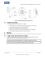
Figure 2 Keypad Reader Dimensions and Mounting


2.1


Mullion Mounting 

The following describes how the readers mount to a mullion.  

1.  Drill two holes 6-32 or M-3 sheet metal or thread forming screws 3.3” (8.38 cm) apart.  

2.  Locate and drill a 0.375” (0.95 cm) hole for the reader cable.  

3.  Route the cable through the center hole to the controller.  

4.  Using the two 6-32 or M-3 screws, attach the reader to the first two mounting holes.  

5.  Once the reader module is screwed in place, snap on the bezel. 

3


Wiring 

3.1


Cable Types and Maximum Lengths 

The MIFARE readers require a minimum voltage of 9.0 VDC. Voltage drops, caused by the cable 
resistance, can be made by increasing the power supply voltage.  

CAUTION: DO NOT SET THE POWER SUPPLY VOLTAGE TO HIGHER THAN 16 VDC. 


CAUTION: DO NOT USE CABLES WITH GAUGES SMALLER THAN 24 AWG: 

February 5, 2007 


Page 5 of 8 

© 2007 HID Global Corporation.  All rights reserved. 


Summary of Contents for FlexSmart 607 Series

Page 1: ...292 Jeronimo Road Irvine CA 92618 1905 HID FlexSmart 607X Series Readers INSTALLATION GUIDE 2007 HID Global Corporation All rights reserved February 5 2006 Document Number 6075 900 Document Version B...

Page 2: ...tents 1 Overview 3 2 Mounting 4 3 Wiring 5 Regulatory 7 Models 7 Contact 8 List of Figures Figure 1 Reader Dimensions and Mounting 4 Figure 2 Keypad Reader Dimensions and Mounting 5 Page 2 of 8 Februa...

Page 3: ...with FlexSmart readers 1 Installation Guide 2 MIFARE reader module for Slim or Wall switch 3 Cover Bezel reader only 1 3 Specifications Supply Voltage 9VDC to 16VDC Supply Current 15 75mA Keypad 25 1...

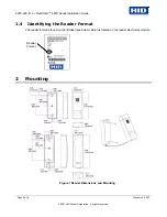
Page 4: ...ing the Reader Format The reader format is found on the ID label see below which is located on the reader electronics module Reader Format 2 Mounting Figure 1 Reader Dimensions and Mounting Page 4 of...

Page 5: ...le to the controller 4 Using the two 6 32 or M 3 screws attach the reader to the first two mounting holes 5 Once the reader module is screwed in place snap on the bezel 3 Wiring 3 1 Cable Types and Ma...

Page 6: ...ke certain the DC resistance between your established earth ground and the system ground is 50 Ohms or less If a direct connection to a ground rod is not possible connect the reader to an earth ground...

Page 7: ...rference received including interference that may cause undesired operation Changes or modifications not expressly approved by the party responsible for compliance could void the user s authority to o...

Page 8: ...90 Europe Middle East and Africa HID Corporation Ltd Haverhill UK email eusupport hidcorp com main 44 0 1440 714 850 support 44 0 1440 711 822 fax number 44 0 1440 714 840 Asia Pacific HID Asia Pacifi...

Reviews: