background image

5

Replacing the Chamber Block

HP

HP-

100

/

120

REPLACING THE CHAMBER BLOCK

STEP

12

STEP

12

STEP

13

STEP

13

STEP

14

STEP

14

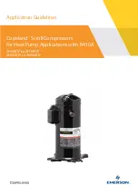
Mount  the  casing  block  with  screws  (4  screws  on 

each side). 

And insert L-tube into the nozzle of casing A. 

Then, fix it with hose clip. 

Complete the other casing block in the same way.

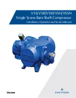
Fit the actuating rod by aligning it with the groove 

and tighten U-lock nut and flat washer by the nut 

driver. 

●Use new U-lock nut and washer, otherwise, U-lock nut 

may work loose and cause malfunction.

Insert the actuating rod into the machine body. Be 

sure  to  fit  the  positioning  boss  on  the  diaphragm 

base into the concave part of the frame stay. 

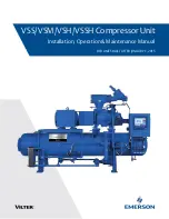
Secure  the  diaphragm  mounting  block  on  the 

other  side  and  tighten  washers  and  U-lock  nuts 

with the nut driver. 

Make  sure  that  gap  between  the  actuating  rod 

and the electromagnets is even.

STEP

15

STEP

15

Check that the broken pin is removed from unit. 

●If the broken pin is left inside the unit, it can get caught 

in  between  electromagnets  and  actuating  rod,  which 
can cause breakdown.

FITTING THE CHAMBER BLOCKS

REPLACEMENT OF SAFETY PIN

Summary of Contents for hp-100

Page 1: ...g Sound Absorber Lap Casing Block A Valve Chamber packing Casing Block B Valve Diaphragm Ring Diaphragm Diaphragm Base Frame Cover SP Switch Safety pin Locking collar Electromagnet Actuating Rod L Tub...

Page 2: ...ore be sure to remove your watch and any other precision machines before operation as they may be affected by the strong magnetic force Do not put the actuating rod close to a magnetic card magnetic d...

Page 3: ...must be broken to prevent any further damage to the pump Be sure all broken pieces are removed from the unit See Step 15 Remove the 4 screws holding the chamber block and the casing block 4 screws on...

Page 4: ...the valves from the casing B If it is difficult to separate them insert the tip of a flatblade screwdriver into the clearance Pull out the valves as they can be removed easily STEP 10 STEP 10 Insert e...

Page 5: ...r otherwise U lock nut may work loose and cause malfunction Insert the actuating rod into the machine body Be sure to fit the positioning boss on the diaphragm base into the concave part of the frame...

Page 6: ...cking collar from the other side of the terminal and insert it until it clicks STEP 18 STEP 18 This completes the replacement of the safety pin procedure Make sure the gap between L shaped lever and t...

Page 7: ...20 STEP 21 STEP 21 Install the sound absorber Place the upper housing back on body Be extremely careful not to catch the sound absorber on the upper housing Fasten it with the bolts Then place the fi...

Page 8: ...It is better to let an experienced technician handle the soldering process Take precautions against getting burned STEP 1 STEP 1 Cut the wire from the terminals on electromag nets with nippers It is r...

Page 9: ...e terminals Solder the wires to the terminals The wire requires a soldered connection Mount new the electromagnets in the unit Tighten up nuts with nut driver STEP 7 STEP 7 This completes the electrom...

Reviews: