background image

BS3 USV User Manual 

Positioning 

Device 

V90Plus GNSS Mainframe 

GNSS Antenna Cable 

Differential Antenna 

Extendable Pole 

Case 

Controller case 

Hull Packaging Aviation Case 

Surveying the W

orld, Mapping the Future

Summary of Contents for iBoat BS3

Page 1: ...BS3 USV User Manual iBoat BS3 User Manual Hi Target Surveying Instrument Co Ltd All Rights Reserved Surveying the W orld M apping the Future ...

Page 2: ...BS3 USV User Manual II Manual Revision Revision Date Revision Level Description Aug 2020 2 iBoat BS3 User Manual 1 1 Version Surveying the W orld M apping the Future ...

Page 3: ...rash and even endanger your own personal safety Exclusions Before using this product please be sure to read the instruction manual carefully which will help you to use this product better Hi Target shall not be liable for any loss caused by mishandling the product if you fail to operate it in accordance with the requirements of the instruction manual or fail to correctly understand the requirement...

Page 4: ... 1 Purchasing Hi Target products you will find this manual in the instrument container to guide you on operating the instrument 2 Logging onto the Hi Target official website to download the electronic version introduction at Partners Partner center Advice If you have any comments and suggestions for this product please email info hi target com cn Your feedback will help us to improve the product a...

Page 5: ...2 5 2 Serial Port Debug 11 2 5 3 Equipment Connection 16 2 6 USV Ground Control Software USV GCS 17 2 7 Preparation for Surveying 22 2 7 1 Coordinate Parameters Configuration 23 2 7 2 Boat Shape Design 23 2 7 3 Draft Setting 24 2 8 Launch the Boat 25 2 9 Surveying 26 2 10 Stop the Recording 27 2 11 Retrieve Boat 27 2 12 Data Post processing 27 2 12 1 Sampling 27 2 12 2 Data Correction 29 2 12 3 Re...

Page 6: ...proving the monitoring efficiency and accuracy reducing the risk of monitoring staff working on the water And lightweight easy to carry Professional hull design high performance sounding module high precision positioning system USV control software and data processing software are independently designed and developed by Hi Target High integration outstanding overall performance coupled with a soun...

Page 7: ...l Figure 1 1 Complete view antenna description Description of ashore station Differential Data Transmission Antenna GNSS Antenna Controller Antenna 2 4GHz Data Transmission Antenna 5 8GHz 360 PTZ Camera Power Switch Charging Port ADCP Port Battery Module Surveying the W orld M apping the Future ...

Page 8: ...t laptop ethernet port can be connected by a network cable which works as a LAN cable Two 5 8 GHz data transmission antennas are equipped in the Ashore station to connect with the USV Working Base Ashore Station omni direction Antenna Remote Controller Ashore Station omni direction Antenna Surveying the W orld M apping the Future ...

Page 9: ... power supplier also the screen indicates power and related information The green grids indicate the power left in the battery Users need to notice that the Power Switch button should be turned on when the battery charge or discharge Charging Port Discharging Port Battery Indicator Power Switch POE Port LAN Port Surveying the W orld M apping the Future ...

Page 10: ... is in the middle position the USV is in cruise mode and will move forward at the set speed uniformly The operator can control the boat s forward direction with the direction stick When the stick is on the far right the USV is in manual mode and the operator needs to control it manually Direction Control Stick Control the USV to turn left or right Overall Operation Flow 2 1 Power on Controller Cli...

Page 11: ...4 to 192 168 1 88 the mask will set as 255 255 255 0 automatically Keep others as default like the following figure and confirm the settings If using a Wi Fi connection the Wi Fi name is the router and the password is 12345678 In addition to changing the IP address and subnet mask you need to change the default gateway to 192 168 1 1 and then confirm the settings Figure 2 3 1 LAN IP setting Survey...

Page 12: ...n the program immediately Add a new virtual serial ports as below Figure2 4 1 Virtual serial port configuration Three Virtual Serial Port configuration as follows Port Function Boat control Virtual COM COM3 can be customized Net Protocol TCP Client Remote IP 192 168 1 18 Remote Port 7000 Surveying the W orld M apping the Future ...

Page 13: ...t Protocol TCP Client Remote IP 192 168 1 18 Remote Port 9000 Figure2 4 2 Connecting status When the ports set up The Connected will be displayed and data income increase if everything goes well Minimize it and keep the program running in the background 2 5 Setup GNSS Receiver by Hi MAX Firstly insert the Hi MAX dongle the orange color one into the laptop register if necessary Surveying the W orld...

Page 14: ...anual 10 Figure 2 5 1 Main interface of Hi Max 2 5 1 New Project Figure 2 5 2 New project creating The project name is at the top of the project list once it had been created Surveying the W orld M apping the Future ...

Page 15: ...2 5 2 Serial Port Debug Figure 2 5 3 Serial port debug Click Connect GPS button Figure 2 5 4 GPS connecting Set the correct parameters and choose the right receiver type click Connect Surveying the W orld M apping the Future ...

Page 16: ...estart the receiver if a license is applied Click SetRover Button Figure 2 5 6 Rover setting Select the DataLink format If there is the base station choose the Built in Radio mode Click Setting and enter the channel number in the pop up Radio Setting window Click OK for conforming Surveying the W orld M apping the Future ...

Page 17: ...BS3 USV User Manual 13 Figure 2 5 6 Radio setting If use CORS select the Built in Wireless mode Figure 2 5 6 Built in wireless Click Setting Surveying the W orld M apping the Future ...

Page 18: ...rresponding IP address port and so on click Apply Figure 2 5 8 Message setting The differential message selects RTCM3 0 and click Apply The shipboard mobile station operation has been completed The next step is data debug Surveying the W orld M apping the Future ...

Page 19: ...he Send button The data in the left window will stop updating Then send GGA position statement ZDA time statement RMC magnetic declination VTG for low speed four commands respectively and set each command frequency as 5HZ Close the window when you are done Surveying the W orld M apping the Future ...

Page 20: ...nnection Choose the correct COM port for example COM3 for GNSS connection choose GPS type as K10 keep baud rate as 19200 antenna type is 0 45m example and test if the signal can come in and printed The NMEA GGA ZDA RMC VTG are necessary Surveying the W orld M apping the Future ...

Page 21: ...ect the serial port number 7000 like COM1 Then set the Baud rate as 57600 and click Connect When the connection is successful enter the Setting interface Figure 2 6 2 Setting interface In the Setting interface users can switch the language Map Provider Speed Units Safe voltage Safe remote Safe GCS etc Surveying the W orld M apping the Future ...

Page 22: ...s users can view the video in the USV GCS HiMax Sounder software and on the web page Figure 2 6 3 Video Config When setting the video access IP should be set as 192 168 1 64 Port should be set as 8000 LoginName should be set as admin Password should be set as zhd123456 Surveying the W orld M apping the Future ...

Page 23: ...the speed of auto cruising We recommend a speed value of 1 5m s for automatically cruising Every time the value is changed you must click the Write button again so that the ship control system can receive the new speed command Notice In any circumstances users can switch between the automatic mode and manual mode by using the controller It means that the manual control right can be obtained urgent...

Page 24: ... the interface and select the save track button to get the current location of the USV Figure 2 6 6 WayPoint setting Label points can be added and edited by mouse five label points are shown in the above figure and then click the Write WPs and Read WPs in sequence from 1 to 5 Back to the Mission interface and click the Auto button to make the USV sail automatically from 1 to 5 Secondly click the A...

Page 25: ...The route planning is completed to this step back to the Mission interface then click the Auto button the boat will start cruise along the planned route automatically When the auto pilot tasks along the planned route are completed the boat status in the left of the main interface will show HOLD At this point shake the mode switch button on the remote control switch the mode to Manual and control t...

Page 26: ...ut The route will be generated automatically Other Functions Load WPs Load the existing WayPoints file Save WPs Save the planned WayPoints as a new file Read WPs Read the saved WayPoints from the hardware Write WPs Write the planned WayPoints to the hardware Clear all Clear all of the WayPoints on the map Save offline map Save the offline map of the WayPoints 2 7 Preparation for Surveying After pl...

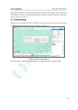
Page 27: ...ure 2 7 1 Coordinate parameters configuration Configure the local ellipsoid coordinate system projection and transformation parameters etc then click the Save button and the set parameters will be saved in files Then turn off the configuration window 2 7 2 Boat Shape Design Figure 2 7 2 Boat shape design Surveying the W orld M apping the Future ...

Page 28: ... on the boat s central axis Starboard Positive value is 0 2 7 3 Draft Setting Open the Survey function in Hi max Click the Sounder button in the menu bar and pop up the configuration form about this surveying as shown in figure 2 7 3 Figure 2 7 3 Sounder interface The user needs to enter the draft value and the recommended value is 0 08m for BS3 Surveying the W orld M apping the Future ...

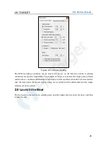
Page 29: ...he single point solution and the above conditions Differential and Fixed are both recorded when the Fixed is selected only the data under the fixed solution status are recorded and the differential and the single solution are not recorded 2 8 Launch the Boat Put the boat into the water at a suitable place and then make the bow enter the water and then release the hull Surveying the W orld M apping...

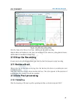
Page 30: ...utoGain and AutoThre When in special circumstances such as in shallow areas the user can adjust the gain and threshold manually The higher the gain the higher the echo amplification gain the higher the threshold and the greater the filtering strength For example when the water depth is 0 6 meters the gain value is recommended 25 and the threshold value is recommended 7 After the above settings are...

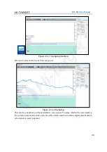
Page 31: ...e measurements just click the Start button again to stop recording 2 11 Retrieve Boat When retrieving the boat after surveying drive the boat near the shore at a suitable place and turn off the power Note First make the stern go ashore and then the bow This is the opposite of the operation of launching the boat finally turn off the controller 2 12 Data Post processing 2 12 1 Sampling Click the Sam...

Page 32: ...nd open it Figure 2 12 2 Sampling This chart is a depth map without simulative echo signals To judge whether the water depth is true or false users need to click on the ShowWave button and then combine digital and simulative echo signals to assist judgment Surveying the W orld M apping the Future ...

Page 33: ...ve display window to check the place where the blue line does not match the red line If there is no match users need to hold down and drag the blue line with the left mouse button to match the red one manually The next step is a sampling There are two sampling methods for users to choose in Sampling Settings If users choose the model just enter a proper interval according to needs and then click S...

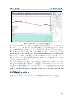
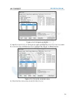
Page 34: ...lay correction The Delay Correct is a correction for GPS resolution and data transmission delay The impact of time delay on bathymetric data can be reduced by Delay Correction The time delay value for the same set of sounding systems is fixed sensors of the bathymetric system are unchanged and the time delays vary from one sounding system to another Figure 2 12 5 Correct interface Surveying the W ...

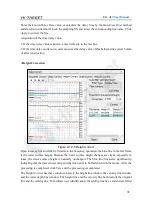
Page 35: ... to the Sampling operation the blue line in the left frame is the water surface height Because the water surface height changes are slight especially in lakes the water surface height is basically unchanged The blue line fluctuates significantly indicating that the data is inaccurate and the line needs to be flattened with the mouse After the processing is completed click Save and the processing i...

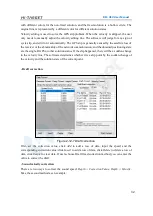
Page 36: ... the single DGPS or other solution status If the slip happened there will be a sudden change in the velocity line The software determines whether it is a slip point by the sudden change of the velocity and the solution state of the current point Draft correction Figure 2 12 7 Draft correction First set the correction value click Add to add a row of data input the speed and the corresponding correc...

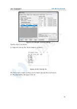
Page 37: ... steps are as follows 1 Import the velocity file the file format is as follows Figure 2 12 9 Velocity file The first column is depth and the second column represents the sound velocity 2 The imported file will appear in the list Surveying the W orld M apping the Future ...

Page 38: ...t during measurement and click Get Correction Value to calculate the correction value of different sections according to the velocity of different depths Figure 2 12 11 Get the correction value 4 Check the files to be corrected and click Start Correct Surveying the W orld M apping the Future ...

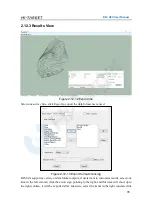
Page 39: ...2 13 Export format choosing Hi MAX supports a variety of data format outputs if users want to customize results select one item in the left column click the arrow sign pointing to the right and this item will show up in the right column it will be exported after Likewise select the items in the right column click Surveying the W orld M apping the Future ...

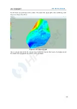
Page 40: ...the export path after confirming click Export or choose ResultView Figure 2 12 14 Result View Select a proper interval for the contour map Select the contents that need to be displayed and the underwater topographic map above can be generated Surveying the W orld M apping the Future ...

Page 41: ...itting antenna Software Dongle Ground Control System GCS 1 Hi MAX Echo Sounder 1 Ashore Base System Intelligent Controller 1 Including 1 internal battery and charger IBoat GCS Software 1 Ashore Wireless Bridge Base 1 Base Battery 1 Including charger Ashore Station Antenna 1 5 8GHz transmitting antenna Network Cable 2 Including one cable Professional USV Echo Sounder HD 510 USV Echo Sounder 1 High ...

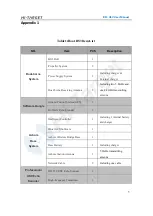
Page 42: ...er Manual 2 Positioning Device V90Plus GNSS Mainframe 1 GNSS Antenna Cable 1 Differential Antenna 1 Extendable Pole 1 Case Controller case 1 Hull Packaging Aviation Case 1 Surveying the W orld M apping the Future ...

Reviews: