HGST Ultrastar Serv24-HA User Manual Download Page 74

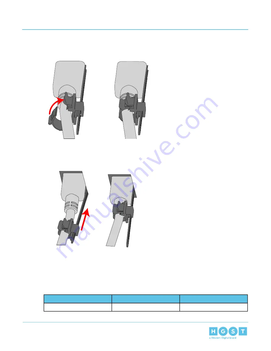
d) Loop the retention clip around the cable and pinch it until the clip catches and locks in place.

Figure 98: Cable Retention Mechanism

e) Slide the retention clip forward until it stops near the cable connector. Doing this will ensure that the

retention clip functions properly in the event the cable is yanked on for some reason.

Figure 99: Cinching Cable Retention Clip

5. Verify the PSU is functional by identifying the PSU LED is no longer indicating a fault. This is indicated by

a green LED on the PSU.

3.9

PIB Canister Replacement

Table 37: Replacement Procedure Info

Time Required

# of People Required

Required Tools

3 minutes

1

None

74

3

Part Replacement

User Guide

3.9

PIB Canister Replacement

Summary of Contents for Ultrastar Serv24-HA

Page 1: ...User Guide Ultrastar Serv24 HA P2522 Version 1 2 August 2018 1ET1089 Long Live Data www hgst com...

Page 2: ...ayout 16 1 6 Ultrastar Serv24 HA Rack Requirements 16 1 7 List of Replaceable Components 17 1 8 LEDs 18 1 8 1 Chassis LEDs 18 1 8 2 PSU LED 19 1 8 3 Drive LEDs 19 1 9 Input Output 20 1 9 1 Rear I O Po...

Page 3: ...Description 32 2 7 1 Compute Canister Specification 33 2 7 2 Compute Canister Layout 33 2 8 Rails Description 34 2 8 1 Rails Specification 34 2 8 2 Rails Layout 34 2 9 Battery Backup 35 2 9 1 Battery...

Page 4: ...atus of the Enclosure Sensors in Web UI 140 4 3 8 Viewing System Inventory using Web UI 141 4 3 9 Viewing System Logs and Reports in Web UI 144 4 3 10 Identifying the Enclosure using Web UI 148 4 3 11...

Page 5: ...6 6 Rackmountable Systems 163 6 7 Safety and Service 164 6 8 Safety Warnings and Cautions 164 Chapter 7 Regulatory Statements 165 7 1 Europe CE Declaration of Conformity 165 7 2 FCC Class A Notice 16...

Page 6: ...edium 175 Appendix B System Operations Appendices 176 B 1 ESD 176 B 2 System Cooling 176 B 3 Power Requirements 176 B 4 Host Connectivity 177 Appendix C Compatibility 178 C 1 Compatible Operating Syst...

Page 7: ...35 section to the Component Overviews on page 22 Revision 1 1 April 2018 Updated the following List of Replaceable Components on page 17 Revision 1 2 August 2018 Part Replacement on page 36 CFUFlash...

Page 8: ...ct contact Global Service and Support Please be prepared to provide the following information Serial Number S N product name model number and a brief description of the issue Email support hgst com We...

Page 9: ...HGST representative or on the Internet at support hgst com HGST may have patents or pending patent applications covering subject matter in this document The furnishing of this document does not give y...

Page 10: ...roduct that are supported by this document SKUs 1ES1038 1ES1030 1ES1037 1ES1029 1ES1001 1ES1031 1ES1039 1ES1000 1ES1041 1ES1003 1ES1040 1ES1032 1ES1043 1ES1033 1ES1042 1ES0405 1ES1045 1ES1035 1ES1044...

Page 11: ...10 Rack Standard 2U Storage Server 24 NVMe drives Redundant 1800W PSUs Two hot swappable Compute Canisters each list item represents the content of one Compute Canister Contains a Intel Purely platfor...

Page 12: ...1 2 Block Diagrams Figure 2 Enclosure System Block Diagram Figure 3 NVMe Canister Block Diagram 12 1 Ultrastar Serv24 HA Overview User Guide 1 2 Block Diagrams...

Page 13: ...Figure 4 Processor Block Diagram 13 1 Ultrastar Serv24 HA Overview User Guide 1 2 Block Diagrams...

Page 14: ...Summary Table 1 Environmental Specification Summary Operational Non Operational Specification 5 C to 35 C 40 C to 60 C Temperature 20 C per hour max 30 C per hour max Temperature Gradient 14 1 Ultras...

Page 15: ...an the specified maximum input current 80 Plus Platinum PSU Efficiency Table 3 Mechanical Specifications Operational Non Operational Specification 10G 5 ms duration 5 shocks positive and 5 negative in...

Page 16: ...onents The out of band management is controlled through Integrated Remote Management Processor system BMC Each Compute Canister provides a VGA port two USB 3 0 ports 10 GbE ports and a 1 GbE port usin...

Page 17: ...PIB Canisters Rails Full set of fan modules 1EX1027 AC Power Cord 2 5m 1EX1134 Drive Blank 1EX1042 PSU 1800W 1EX1055 Battery Backup 1EX1048 Rails 1EX1049 Compute Canister 1EX1054 PIB Canister 1EX1046...

Page 18: ...n LED Number Off Power off Green Power on Power 1 Off Chassis is not being identified Blue Chassis is being identified Identify 2 Off No faults reported Amber 1Hz Blinking Warning error Amber 4Hz Blin...

Page 19: ...lt failure or AC disconnection on PSU 1 8 3 Drive LEDs Figure 9 Drive LEDs Top View 1 2 Table 9 Drive LEDs Action LED Number Off No drive present Green Drive present Green Blinking Drive active Drive...

Page 20: ...es Port Number PSU x2 1 USB 3 0 2 USB 3 0 3 1 GbE for IPMI RJ45 4 10 GbE RJ45 5 VGA Port DB 15 6 100 GbE QSFP28 7 10 GbE RJ45 8 Serial UART Port 9 1 10 List of Compatible Drives Table 11 Compatible Dr...

Page 21: ...1EX1040 3 84 TB HGST Ultrastar SN200 RI 1DW D SE 1EX1041 7 68 TB HGST Ultrastar SN200 RI 1DW D SE 1EX1026 256 GB SanDisk X400 SSD M 2 2280 Boot Drive 21 1 Ultrastar Serv24 HA Overview User Guide 1 10...

Page 22: ...torage drives The rear of the chassis contains PSU bays and two Compute Canisters The major system components such as the fan modules CPUs memory and M 2 Boot Drives are all contained within each of t...

Page 23: ...er Interface Board PIB Canister houses the PIB that extends the connection of the PSU to the midplane The PIB Canister contains a connector on the PSU end that attaches to the PIB and finishes at the...

Page 24: ...1 58in x L 28 1in x H 3 06in Dimensions 1EX1054 Part Number No Hot Swappable 1 36 kg 3 lbs Weight 2 2 2 PIB Canister Layout Figure 14 PIB Canister Layout Rear Front Top 1 2 3 4 Table 15 PIB Canister...

Page 25: ...C The PSUs are 80 Plus Platinum certified and utilize C14 power cable receptacles 2 3 1 PSU Specifications Table 16 PSU Specification Summary Value Specifications 1800W Power Output 80 Plus Platinum 8...

Page 26: ...2 PSU Layout Figure 16 PSU Layout 1 2 3 4 5 Table 17 PSU Layout Feature Number Latch Release Lever 1 Power Receptacle 2 Fan 3 Handle 4 Connector 5 26 2 Component Overviews User Guide 2 3 PSU Descript...

Page 27: ...hes to the exterior of the data storage drive and caddies the drive into the system It stabilizes the motion of the drive into the drive cage so that the drive properly mounts onto the drive board 2 4...

Page 28: ...ve Layout Figure 18 Drive Layout 1 2 3 4 5 Table 19 Drive Layout Feature Number Drive 1 Drive Carrier 2 Carrier Handle 3 Latch Release Button 4 LEDs 5 28 2 Component Overviews User Guide 2 4 Drive Des...

Page 29: ...as to ensure that the enclosure has the ability to run efficiently The enclosure can contain up to 14 Drive Blank Assemblies with the remaining 10 drive bays populated with functioning Drive Assemblie...

Page 30: ...igure 20 Drive Blank Layout 1 3 2 4 Table 21 Drive Blank Assembly Layout Feature Number Drive Blank 1 Drive Carrier 2 Latch Release Button 3 Drive Carrier Latch 4 30 2 Component Overviews User Guide 2...

Page 31: ...the compute canister components to provide efficient cooling to all of the drives Each compute canister contains five fans two in the middle and three near the rear of each canister 2 6 1 Fan Specific...

Page 32: ...ter Description Figure 23 Compute Canister Description The chassis contains redundant Compute Canisters that each house and connect system components that comprise the Ultrastar Serv24 HA The major sy...

Page 33: ...is always available 2 7 1 Compute Canister Specification Table 24 Compute Canister Specification Summary Value Specification 2 Number Per Enclosure 1EX1049 Part Number Yes Hot Swappable 9 34 kg 20 6 l...

Page 34: ...ks are easily unlatched to provide the option to pull the enclosure out of the rack to service the contents of the chassis 2 8 1 Rails Specification Table 26 Rails Specification Summary Value Specific...

Page 35: ...heet metal case also contains a keyholes on the bottom of the model to secure the battery backup in place and connected to the Compute Canister This module can be installed into each of the Compute Ca...

Page 36: ...the drive assembly a Release the drive assembly by pressing the button on the drive carrier and lower the carrier release until it stops Figure 28 Drive Carrier Release Press b Pull the drive assembl...

Page 37: ...nection with the connector on the drive board without causing damage Figure 31 Drive Assembly Lever 4 Verify the drive is functional by verifying the Amber drive carrier LED is no longer indicating a...

Page 38: ...Blank Assembly 3 Install the drive blank assembly a Open the drive blank carrier release by pressing the button on the drive blank carrier b With the drive blank carrier button on top slide the drive...

Page 39: ...he Web UI will appear Figure 35 Web UI b In the Web UI click Dashboard The Dashboard Control Panel page will appear Figure 36 Dashboard Control Panel c Review the Dashboard Control Panel to identify t...

Page 40: ...clear of the enclosure Figure 38 Uninstalling the Compute Canister 3 Uninstall the Compute Canister cover a Unlock the Compute Canister cover by pressing the two lock buttons and slide the cover towa...

Page 41: ...tion of each DIMM as it is removed to ensure that it is installed into the correct location of the replacement Compute Canister 5 Install the DIMM into the Compute Canister a Slide the DIMM into the c...

Page 42: ...installed with the top cover facing toward the bottom of the enclosure The bottom Compute Canister is installed with the top cover facing the top of the enclosure b Carefully slide the Compute Caniste...

Page 43: ...nel to identify that there are no failures reported 3 4 CPU and Heat Sink Module Replacement Table 32 Replacement Procedure Info Time Required of People Required Required Tools 20 minutes 1 T30 Torx s...

Page 44: ...e 47 Dashboard Control Panel c Review the Dashboard Control Panel to identify the failed CPU 2 Uninstall the Compute Canister from the enclosure a From the rear of the enclosure determine which of the...

Page 45: ...49 Uninstalling the Compute Canister 3 Uninstall the Compute Canister cover a Unlock the Compute Canister cover by pressing the two lock buttons and slide the cover towards the rear of the Compute Ca...

Page 46: ...y loosening the Torx T30 screws in a specific order Use the following diagram to determine the specific order Figure 50 Heat Sink Removal Order 4 3 2 1 Pin Pin 46 3 Part Replacement User Guide 3 4 CPU...

Page 47: ...ule a Locate the socket alignment pin on the baseboard and the alignment hole on the Heat Sink b Carefully place the CPU and Heat Sink module in position on the socket alignment pins c The Heat Sink m...

Page 48: ...tened to a torque setting of 12in lbs Do not over tighten Over tightening may cause damage to the parts Figure 52 Install CPU Figure 53 Heat Sink Installation Order 48 3 Part Replacement User Guide 3...

Page 49: ...cover is secure 9 Install the Compute Canister into the enclosure a From the rear of the enclosure line up the Compute canister with the empty canister slot Ensure that the Compute Canister is orient...

Page 50: ...54 Installing the Compute Canister c Rotate the latch handles into the enclosure until the are fully engaged Figure 55 Latching the Compute Canister 10 Verify that the CPU appears with no issues a Op...

Page 51: ...ntrol Panel to identify that there are no failures reported 3 5 Heat Sink Replacement Table 33 Replacement Procedure Info Time Required of People Required Required Tools 30 minutes 1 Torx T30 Screwdri...

Page 52: ...igure 59 Dashboard Control Panel c Review the Dashboard Control Panel to identify the failed Heat Sink 2 Uninstall the Compute Canister from the enclosure a From the rear of the enclosure determine wh...

Page 53: ...e Figure 61 Uninstalling the Compute Canister 3 Uninstall the Compute Canister cover a Unlock the Compute Canister cover by pressing the two lock buttons and slide the cover towards the rear of the Co...

Page 54: ...moved by loosening the Torx T30 screws in a specific order Use the following diagram to determine the specific order Figure 62 Heat Sink Removal Order 4 3 2 1 Pin Pin 54 3 Part Replacement User Guide...

Page 55: ...Heat Sink Figure 64 Removing the CPU from the Heat Sink with a Spudger b Insert the edge of a plastic spudger in between the CPU and Heat Sink and carefully pry the two components apart The plastic sp...

Page 56: ...d snap the CPU into the plastic CPU retainer Figure 65 CPU and CPR Retainer Triangles c Unpack and remove the protective plastic tray that is attached to the bottom of the Heat Sink The protective pla...

Page 57: ...pin on the baseboard and the alignment hole on the Heat Sink b Carefully place the CPU and Heat Sink module in position on the socket alignment pins c The Heat Sink must be installed by tightening th...

Page 58: ...be tightened to a torque setting of 12in lbs Do not over tighten Over tightening may cause damage to the parts Figure 67 Install CPU Figure 68 Heat Sink Installation Order 58 3 Part Replacement User G...

Page 59: ...and the cover is secure 11 Install the Compute Canister into the enclosure a From the rear of the enclosure line up the Compute canister with the empty canister slot Ensure that the Compute Canister i...

Page 60: ...igure 69 Installing the Compute Canister c Rotate the latch handles into the enclosure until the are fully engaged Figure 70 Latching the Compute Canister 12 Verify that the Heat Sink appears with no...

Page 61: ...edure Info Time Required of People Required Required Tools 12 minutes 1 None Attention The compute canister contains a total of two M 2 boot drives with a total of four per enclosure Only one set of d...

Page 62: ...oard The Dashboard Control Panel page will appear Figure 74 Dashboard Control Panel c Review the Dashboard Control Panel to identify the failed boot drive 2 Uninstall the Compute Canister from the enc...

Page 63: ...lling the Compute Canister 3 Uninstall the Compute Canister cover a Unlock the Compute Canister cover by pressing the two lock buttons and slide the cover towards the rear of the Compute Canister b Re...

Page 64: ...anister cover a Align the cover over the Compute Canister and slide towards the front of the Compute Canister b Verify the locks on the cover have engaged and the cover is secure 8 Install the Compute...

Page 65: ...gure 79 Installing the Compute Canister c Rotate the latch handles into the enclosure until the are fully engaged Figure 80 Latching the Compute Canister 9 Verify that the M 2 boot drive appears with...

Page 66: ...ashboard Control Panel to identify that there are no failures reported 3 7 NIC Replacement Table 35 Replacement Procedure Info Time Required of People Required Required Tools 10 minutes 1 0 screwdrive...

Page 67: ...r Figure 84 Dashboard Control Panel c Review the Dashboard Control Panel to identify the failed enclosure 2 Uninstall the Compute Canister from the enclosure a From the rear of the enclosure determine...

Page 68: ...the Compute Canister 3 Uninstall the Compute Canister cover a Unlock the Compute Canister cover by pressing the two lock buttons and slide the cover towards the rear of the Compute Canister b Remove t...

Page 69: ...om the NIC b From the rear of the enclosure remove the screws that secure the NIC plate in place and remove the NIC plate c From inside the enclosure lift the NIC up and out of the enclosure Figure 88...

Page 70: ...losure board with the provided screws Figure 90 Secure NIC with Screws 7 Install the corner PCIe bracket by carefully lining up the sheet metal carrier on the guides and pressing it into the bracket 8...

Page 71: ...ister into the slot with both latch handles in the open position until the latch handles begin to engage Figure 91 Installing the Compute Canister c Rotate the latch handles into the enclosure until t...

Page 72: ...red Required Tools 5 minutes 1 None 1 Locate the failed PSU by identifying the illuminated Amber LED on the PSU 2 From the rear of the enclosure disconnect the power cord connected to the PSU a Detach...

Page 73: ...uld not be removed from the enclosure unless it has been identified as a failed part Figure 96 Removing the PSU 4 Install the PSU into the chassis a Align the PSU in the orientation shown in the follo...

Page 74: ...tion clip functions properly in the event the cable is yanked on for some reason Figure 99 Cinching Cable Retention Clip 5 Verify the PSU is functional by identifying the PSU LED is no longer indicati...

Page 75: ...e 100 Cable Retention Mechanism b Remove the power cord by pulling firmly but do not jerk it out of the unit 3 Uninstall the PSU from the chassis a Unlock the PSU by pressing the PSU release latch Fig...

Page 76: ...Locate the gray tab just below the location of the uninstalled PSU b Grasp the tab firmly and carefully pull the PIB Canister until the card edge comes out of the midplane Figure 103 Removing the PIB...

Page 77: ...onnector d Verify that the PIB Canister is seated snugly 6 Install the PSU into the chassis a Align the PSU in the orientation shown in the following image b Slide the PSU into the slot until it seats...

Page 78: ...l ensure that the retention clip functions properly in the event the cable is yanked on for some reason Figure 107 Cinching Cable Retention Clip 3 10 Rails Replacement Table 38 Replacement Procedure I...

Page 79: ...er cord out of the remaining PSU 3 Disconnect the remaining cables from the rear of the enclosure 4 Remove the Rack Ears from the enclosure a Locate finger hold on the lower half of the rack ear b Ins...

Page 80: ...Removing the Rack Ear d Repeat the previous procedure to remove the remaining rack ear 5 Remove the enclosure from the rack a Locate the shipping screws that are installed below the thumbscrews on th...

Page 81: ...ving the Shipping Screws c Locate the thumbscrews on either side of the enclosure d Loosen the thumbscrews by turning them counterclockwise until they are free of the rail connection Figure 112 Loosen...

Page 82: ...e Enclosure 6 Uninstall the Rails from the rack a Locate the shipping screws that are installed on the rear rail connections b Remove screws from rails using a 1 Philips screwdriver c Open the front l...

Page 83: ...rear latch by pulling the tab and rotating the latch open until it is at 90 degrees Figure 116 Rail Unlatched Right Side f Pull the rear rail connection free of the rack posts g Repeat the previous p...

Page 84: ...tom 1U of the installation location c Place rear pins of the rail into rear rack post d Secure the rear rail attachment to the rear rack post by rotating the rear latch until it clips over the rear ra...

Page 85: ...ch until it clips over the rear rack post Figure 120 Rail Latched h Secure the rear rail attachment to the rack post using two of the provided shipping screws Figure 121 Install Shipping Screws i Repe...

Page 86: ...ted against the rack mounted rails Figure 122 Installing the Enclosure b Locate the thumbscrews on either side of the enclosure c Press and tighten the thumbscrews by turning them clockwise until snug...

Page 87: ...the enclosure b Place the top of the rack ear on the tab of the sheet metal bracket and rotate toward the bottom tab Figure 125 Rack Ear Install c Lightly pull on the rack ear to ensure that it fully...

Page 88: ...ly powered on from a laptop log into the Web UI c In the Web UI click Dashboard The Dashboard Control Panel page will appear Figure 126 Dashboard Control Panel d Verify that the reported failure no lo...

Page 89: ...ure 127 Power Control c Select the option next to Power Off and click Perform Action A message Are you sure to perform this operation will appear Figure 128 Are You Sure d Click OK 89 3 Part Replaceme...

Page 90: ...he second server using the assigned IP Address f In the Web UI click Power Control The Power Control page will appear Figure 130 Power Control g Select the option next to Power Off and click Perform A...

Page 91: ...ration will appear Figure 131 Are You Sure h Click OK The enclosure will Power Off Figure 132 Power Off 2 From the rear of the enclosure disconnect the power cord connected to the PSU 91 3 Part Replac...

Page 92: ...r cord out of the remaining PSU 4 Disconnect the remaining cables from the rear of the enclosure 5 Remove the Rack Ears from the enclosure a Locate finger hold on the lower half of the rack ear b Inse...

Page 93: ...Removing the Rack Ear d Repeat the previous procedure to remove the remaining rack ear 6 Remove the enclosure from the rack a Locate the shipping screws that are installed below the thumbscrews on the...

Page 94: ...ing the Shipping Screws c Locate the thumbscrews on either side of the enclosure d Loosen the thumbscrews by turning them counterclockwise until they are free of the rail connection Figure 137 Looseni...

Page 95: ...the rack mounted rails Figure 138 Uninstalling the Enclosure 7 Uninstall the PSU from the chassis a Unlock the PSU by pressing the PSU release latch Figure 139 PSU Release Latch PRESS b Remove the PSU...

Page 96: ...a Locate the gray tab just below the location of the uninstalled PSU b Grasp the tab firmly and carefully pull the PIB Canister until the card edge comes out of the midplane Figure 141 Removing the P...

Page 97: ...Repeat the previous step to uninstall the remaining PSU 11 Locate the PSU slots on the rear of the new enclosure chassis 12 Install the PSU into the chassis a Align the PSU in the orientation shown in...

Page 98: ...anism e Slide the retention clip forward until it stops near the cable connector Doing this will ensure that the retention clip functions properly in the event the cable is yanked on for some reason F...

Page 99: ...eat the previous step to uninstall the remaining drives 15 Locate the drive slots on the front of the new enclosure chassis 16 Install the drive assembly a Open the drive carrier release by pressing t...

Page 100: ...Figure 149 Drive Assembly Lever 17 Uninstall the Compute Canister from the enclosure a From the rear of the enclosure determine which of the two Compute Canisters is in need of replacement b Unlatch t...

Page 101: ...he new enclosure chassis 20 Install the Compute Canister into the enclosure a From the rear of the enclosure line up the Compute canister with the empty canister slot Ensure that the Compute Canister...

Page 102: ...the latch handles begin to engage Figure 152 Installing the Compute Canister c Rotate the latch handles into the enclosure until the are fully engaged Figure 153 Latching the Compute Canister 21 Insta...

Page 103: ...d against the rack mounted rails Figure 154 Installing the Enclosure b Locate the thumbscrews on either side of the enclosure c Press and tighten the thumbscrews by turning them clockwise until snug F...

Page 104: ...the enclosure b Place the top of the rack ear on the tab of the sheet metal bracket and rotate toward the bottom tab Figure 157 Rack Ear Install c Lightly pull on the rack ear to ensure that it fully...

Page 105: ...cally powered on from a laptop log into the Web UI c In the Web UI click Dashboard The Dashboard Control Panel page will appear Figure 158 Dashboard Control Panel d Verify that the reported failure no...

Page 106: ...0 Dashboard Control Panel c Review the Dashboard Control Panel to identify the failed Compute Canister 2 Uninstall the Compute Canister from the enclosure a From the rear of the enclosure determine wh...

Page 107: ...ure 162 Uninstalling the Compute Canister 3 Uninstall the Compute Canister cover a Unlock the Compute Canister cover by pressing the two lock buttons and slide the cover towards the rear of the Comput...

Page 108: ...by loosening the Torx T30 screws in a specific order Use the following diagram to determine the specific order Figure 163 Heat Sink Removal Order 4 3 2 1 Pin Pin 108 3 Part Replacement User Guide 3 1...

Page 109: ...module a Locate the socket alignment pin on the baseboard and the alignment hole on the Heat Sink b Carefully place the CPU and Heat Sink module in position on the socket alignment pins c The Heat Si...

Page 110: ...ghtened to a torque setting of 12in lbs Do not over tighten Over tightening may cause damage to the parts Figure 165 Install CPU Figure 166 Heat Sink Installation Order 110 3 Part Replacement User Gui...

Page 111: ...g heat sink containing the CPU 8 Uninstall the DIMM from the Compute Canister a Pull connector tabs outward with even pressure until the DIMM pops out of the connector Figure 167 Unlocking the DIMM 11...

Page 112: ...anister 10 Install the DIMM into the Compute Canister a Slide the DIMM into the correct DIMM slot and carefully press down until seated b Secure the DIMM by pressing the tabs inward on either side of...

Page 113: ...drive 14 Identify the location of the first M 2 boot drive on the replacement Compute Canister 15 Install the M 2 boot drive a Slide the card edge of the drive into the connector with even pressure b...

Page 114: ...up on the replacement Compute Canister 18 Install the Battery Backup into the Compute Canister a Rotate the Battery Backup latch up and out until fully open Figure 173 Open the Battery Backup Latch b...

Page 115: ...owards the front of the Compute Canister b Verify the locks on the cover have engaged and the cover is secure 20 Install the Compute Canister into the enclosure a From the rear of the enclosure line u...

Page 116: ...Installing the Compute Canister c Rotate the latch handles into the enclosure until the are fully engaged Figure 178 Latching the Compute Canister 21 Verify that the Compute Canister appears with no...

Page 117: ...hboard Control Panel c Review the Dashboard Control Panel to identify that there are no failures reported 3 13 Optional Battery Backup Replacement 1 Identify the failed Battery Backup a Open a browser...

Page 118: ...Dashboard Control Panel c Review the Dashboard Control Panel to identify the failed Battery Backup 2 Uninstall the Compute Canister from the enclosure a From the rear of the enclosure determine which...

Page 119: ...nd pulling it clear of the enclosure Figure 184 Uninstalling the Compute Canister 3 Uninstall the Compute Canister cover a Unlock the Compute Canister cover by pressing the two lock buttons and slide...

Page 120: ...n the replacement Compute Canister 6 Install the Battery Backup into the Compute Canister a Rotate the Battery Backup latch up and out until fully open Figure 186 Open the Battery Backup Latch b Line...

Page 121: ...ds the front of the Compute Canister b Verify the locks on the cover have engaged and the cover is secure 8 Install the Compute Canister into the enclosure a From the rear of the enclosure line up the...

Page 122: ...nstalling the Compute Canister c Rotate the latch handles into the enclosure until the are fully engaged Figure 191 Latching the Compute Canister 9 Verify that the Battery Backup appears with no issue...

Page 123: ...click Dashboard The Dashboard Control Panel page will appear Figure 193 Dashboard Control Panel c Review the Dashboard Control Panel to identify that there are no failures reported 123 3 Part Replace...

Page 124: ...rough a command line interface CLI to communicate with the enclosure using simple commands to manipulate settings and functions of the enclosure The IPMI management option uses IPMItool for enclosures...

Page 125: ...and Downloads page using a username and password Note If product has not been registered complete the registration first before continuing Figure 196 Customer Technical Support and Downloads 6 Access...

Page 126: ...ew the firmware download options by clicking Ultrastar Serv24 HA Chassis Firmware 9 Download the firmware by clicking Download next the latest firmware zip file The product firmware will download 10 E...

Page 127: ...eb UI to handle out of band OOB management Web UI is intended to provide ease of control and customization while accessing the Ultrastar Serv24 HA This user interface is designed to easily create new...

Page 128: ...e Web UI has to offer It has the option to remain in the browser at all times for ease of navigation between different functions and can also be hidden to display only the Main Dashboard and Quick But...

Page 129: ...tions Each diagnostic that is displayed in the Dashboard Control Panel can be accessed quickly by clicking the cards 4 3 1 Web UI Supported Browsers Table 41 Supported Web UI Browsers by Operating Sys...

Page 130: ...203 User Management 3 Select an unassigned user card The User Management Configuration Page will appear 4 Configure the required User Settings Username create a Username Password create a Password Ena...

Page 131: ...to all functions within the Web UI The other user privilege levels contain limitations to what functions and features can be accessed or configured Figure 204 User Management Configuration Required F...

Page 132: ...Management Configuration Other User Privileges 6 From the Quick Buttons Bar select admin Sign out A Would you like to Sign out of this Session message will display 7 Click OK The current session will...

Page 133: ...Network Settings in Web UI 1 Log in to the Web UI a Open a browser window and navigate to the Compute Canister BMC IP address b Login to Web UI using the username and password Figure 207 Log in Web UI...

Page 134: ...gs 3 Complete the necessary fields and save 4 3 4 Changing the DNS Configurations in Web UI 1 Log in to the Web UI a Open a browser window and navigate to the Compute Canister BMC IP address b Login t...

Page 135: ...4 3 5 Updating BIOS Firmware in Web UI Important The BIOS and BMC updates must all be updated on the first Compute Canister before completing updates on the second Compute Canister 1 Download the new...

Page 136: ...Figure 211 Log in Web UI will appear displaying the Dashboard Control Panel 3 Navigate to Maintenance BIOS Firmware Update using the Navigation menu Figure 212 Navigate to BIOS Firmware Update 136 4...

Page 137: ...ing message will appear and the Uploading status bar in the background will display the progress of the update The Web UI session will be ended and the BIOS firmware will be updated 4 3 6 Updating BMC...

Page 138: ...l appear displaying the Dashboard Control Panel 3 Navigate to Maintenance Firmware Update using the Navigation menu Figure 216 Firmware Update 4 Select the checkbox next to Preserve all Configuration...

Page 139: ...Figure 217 Preserve all Configuration 5 Browse to the location of the new Firmware image 6 Select the image and click OK The image will appear in the Select Firmware Image section 7 Click Start firmwa...

Page 140: ...s 10 Click OK The Web UI session will be ended 11 Log in to Web UI and navigate to Maintenance BMC Firmware Information Figure 220 BMC Firmware Information 12 Verify that the firmware version displays...

Page 141: ...n menu 3 Select a sensor to view the information for that particular component 4 Change and save Thresholds as needed 4 3 8 Viewing System Inventory using Web UI 1 Log in to the Web UI a Open a browse...

Page 142: ...2 Navigate to System Inventory using the Navigation menu Figure 223 Navigation Menu System Inventory 142 4 System Management User Guide 4 3 Web UI Overview...

Page 143: ...3 View the System Inventory Block Diagram by selecting the Block Diagram option Figure 224 System Inventory Information Block Diagram 143 4 System Management User Guide 4 3 Web UI Overview...

Page 144: ...4 3 9 Viewing System Logs and Reports in Web UI 1 Log in to the Web UI a Open a browser window and navigate to the Compute Canister BMC IP address b Login to Web UI using the username and password Fig...

Page 145: ...ogs a Select a Start Date and End Date from the Filter by Date droplists b Select an Event Type from the All Events droplist c Select a Sensor from the All Sensors droplist d Select the Timezone for t...

Page 146: ...n Menu Logs and Reports 6 Filter the System Logs a Select a Start Date and End Date from the Filter by Date droplists b Select an Alert from the Event Category droplist Figure 230 System Log Filter 7...

Page 147: ...enu Figure 231 Navigation Menu Logs and Reports 9 Filter the Audit Logs by selecting a Start Date and End Date from the Filter by Date droplists Figure 232 Audit Log Filter 10 Review the resulting Aud...

Page 148: ...by selecting a Start Date and End Date from the Filter by Date droplists Figure 234 Video Log Filter 13 Review the resulting Video Logs 4 3 10 Identifying the Enclosure using Web UI 1 Log in to the W...

Page 149: ...displaying the Dashboard Control Panel 2 Navigate to Server Identify using the Navigation menu Figure 236 Server Identify 3 Select Option and perform action 4 3 11 Power Off Reset the Enclosure using...

Page 150: ...name and password Figure 237 Log in Web UI will appear displaying the Dashboard Control Panel 2 Navigate to Power Control using the Navigation menu Figure 238 Power Control 3 Select the option to powe...

Page 151: ...ssued within the different IPMI instances may contain instructions to add user specific content An example of this using IPMItool is seen in the following command ipmitool l lan H IP ADDRESS U USERNAM...

Page 152: ...l lan H IP ADDRESS U admin P admin user list The Terminal will provide a list of active users with the new user at the end of the list 6 Set a password for the new user by issuing the command ipmitool...

Page 153: ...ddr NEW IP ADDRESS The Terminal will display the new IP address 5 Set the netmask by issuing the command ipmitool l lan H IP ADDRESS U admin P admin lan set netmask NETMASK The Terminal will display t...

Page 154: ...splayed Figure 245 Compute Canister Sensors 3 Check the status of the Compute Canister temperature sensors by issuing the command ipmitool l lan H IP ADDRESS U USERNAME P PASSWORD sdr type temperature...

Page 155: ...SSWORD sdr type fan The temperature of the Compute Canister fans will be displayed Figure 247 Fan Temperature Sensors 4 4 1 4 Viewing System Logs and Reports using IPMItool 1 Launch a Terminal by clic...

Page 156: ...power off The Compute Canister will power off 6 Reset the enclosure by issuing the command ipmitool l lan H IP ADDRESS U USERNAME P PASSWORD power reset The Compute Canister will power off and restart...

Page 157: ...navigate to the directory where the CFUFlash executable is located 3 Update the BIOS firmware by issuing the command Cfuflash nw ip IP ADDRESS u USERNAME p PASSWORD FILENAME bin preserve config d 2 YA...

Page 158: ...firmware by issuing the command Yafuflash nw ip IP ADDRESS u USERNAME p PASSWORD FILENAME ima preserve config d 1 YAFUFlash will prompt the user to choose Y or N to upgrade the BMC firmware using the...

Page 159: ...cess is through the use of a tool or lock and key or other means of security and is controlled by the authority responsible for the location 5 3 Regulatory Statement Product Name Ultrastar Serv24 HA R...

Page 160: ...r EN 55024 KN35 KN EN 61000 4 2 ESD KN EN 61000 4 3 Radiated Immunity KN EN 61000 4 4 EFT KN EN 61000 4 5 Surge KN EN 61000 4 6 RF Common Mode KN EN 61000 4 8 Power Frequency Magnetic Field KN EN 6100...

Page 161: ...Authority or Mark Country Region SII Israel 161 5 Disclaimers User Guide 5 5 Country Certifications...

Page 162: ...product can result in lowered system performance or system failure Do not position the unit in an environment that has extreme high temperatures or extreme low temperatures Be aware of the proximity...

Page 163: ...e lithium batteries the following applies if the battery is placed in an OPERATOR ACCESS AREA there shall be a marking close to the battery or a statement in both the operating and servicing instructi...

Page 164: ...e power supply Return to manufacturer for servicing Use caution when accessing part of the product that are labeled as potential shock hazards hazardous access to moving parts such as fan blades or ca...

Page 165: ...ice complies with Part 15 of the FCC Rules Operation is subject to the following two conditions 1 This device may not cause harmful interference 2 This device must accept any interference received inc...

Page 166: ...duct In a domestic environment this product may cause radio interference in which case the user may be required to take adequate measures Table 43 Declaration of the Presence Condition of the Restrict...

Page 167: ...stance exceeds the reference percentage value of presence condition 2 O Note O indicates that the percentage content of the restricted substance does not exceed the percentage of reference value of pr...

Page 168: ...ent Log SEL sel Configure Platform Event Filtering PEF pef Configure and connect IPMIv2 0 Serial over LAN sol Configure and connect with Tyan IPMIv1 5 Serial over LAN tsol Configure IPMIv1 5 Serial ov...

Page 169: ...ONE PASSWORD MD2 MD5 or OEM A authtype Remote session password P password Read password from IPMI_PASSWORD environment variable E Set local IPMB address m address Set destination channel for bridged r...

Page 170: ...et Watchdog Timer 24h App Set Watchdog Timer 25h App Get Watchdog Timer BMC Device and Messaging Commands 2Eh App Set BMC Global Enables 2Fh App Get BMC Global Enables 30h App Clear Message Flags 31h...

Page 171: ...App Set User Payload Access 4Dh App Get User Payload Access 4Eh App Get Channel Payload Support 4Fh App Get Channel Payload Version 52h App Master Write Read 54h App Get Channel Cipher Suites 55h App...

Page 172: ...PEF Configuration Parameters 14h S E Set Last Processed Event ID 15h S E Get Last Processed Event ID 16h S E Alert Immediate 17h S E PET Acknowledge Sensor Device Commands 24h S E Set Sensor Hysteres...

Page 173: ...e Get SEL Info 41h Storage Get SEL Allocation Info 42h Storage Reserve SEL 43h Storage Get SEL Entry 44h Storage Add SEL Entry 46h Storage Delete SEL Entry 47h Storage Clear SEL 48h Storage Get SEL Ti...

Page 174: ...on to interactive upgrade i A 6 CFUFlash Options Displays information about existing FW and new FW info Option to FORCE BootLoader upgrade during full upgrade force boot Option Preserve configuration...

Page 175: ...ons to be preserved or not where XXX falls in sdr fru sel ipmi auth net ntp snmp ssh kvm auth Option to preserve only XXX configuration preserve XXX ignore existing overrides ignore existing overrides...

Page 176: ...case of a warning sensor threshold violation the OTP mechanism will report the warning information to the user through system management protocols If the critical sensor threshold is exceeded the CPU...

Page 177: ...t certified for lowline 100 127VAC operation B 4 Host Connectivity The following table displays the list of power cables approved by HGST Table 46 Approved Power Cables Dimension overmold Part Number...

Page 178: ...en tested and approved for the Ultrastar Serv24 HA Table 48 CPU Agile or Vendor Model Number CPU Vendor Model Intel 8153 Intel Xeon Platinum 8153 SR3BA H0 Stepping 2 00 GHz 3 UPI 10 4GT s 16 Cores 22M...

Page 179: ...odel Intel 3106 Intel Xeon Bronze 3106 QN0C H0 Stepping 1 70 GHz 2 UPI 9 6GT s 8 Cores 11MB 85W Vendor Model Intel 3104 Intel Xeon Bronze 3104 QN0D H0 Stepping 1 70 GHz 2 UPI 9 6GT s 6 Cores 8MB 85W T...

Page 180: ...anDisk X400 SSD M 2 2280 Boot Drive Table 52 Add in Cards Agile or Vendor Model Number Add in Card Vendor Model SAS 9300 8e Broadcom SAS HBA Adapter 12Gb s Mini SAS HD PCIe 3 0 x8 2 Port Vendor Model...

Page 181: ...Mini SAS HD 12G 3m Vendor Model 1110751003 Mini SAS HD Molex SAS Cable Mini SAS HD 12G 3m Vendor Model 1110751001 Mini SAS HD Molex SAS Cable Mini SAS HD 12G 1m Vendor Model MLE10114500018 Mini SAS HD...

Reviews: