background image


Research and Development 

Technical Documentation 

Form Rev. A 

Revision 

Project: 


Page 


Description: 

2400MHz RF Module with Frequency Hopping 

8 of 10 


3.


TECHNICAL SPECIFICATION 

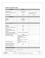
POWER 

VALUE 


Supply Voltage 

2.8 to 4.2 VDC 


Transmit mode Supply Current  

90 mA 

Vcc= 4V, 20 bBm output,  

50 ohm load. 

Receiver Mode  

40 mA 

Vcc= 4V 


PROTOCOL 


Data Rate 

25 kbps 


Buffered 

≥1024 Bytes


PTP 

Yes 


RF 


Diversity 

Full 


Encryption 

Yes 


RSSI and/or LQI available to all 

nodes 

Yes 


Channels available 

200 


Proprietary communications 

protocol 

Yes 


Circular Antenna Polarization 

(external), PCB RF connector only 

RHCP, RF connector SMB type   

Adjustable RF power 

 20 dBm 


Class 1 receiver blocking 

Complies to ETSI 300 328 V2.2.1 

(2019-04), clause: 

Page 26: 4.3.1.12 Receiver 

Blocking 

Page 27: 4.3.1.12.4.2 Receiver 

Category 1 


Receive Noise Figure 

TI LNA: 4,8 dB incl. antenna 

switch 


Robust front-end filtering 

Yes 


Frequency Hopping 

 zero 

application configuration 

Yes 


OPERATING ENVIRONMENT 


Operating Temperature 

-40

°

 to +85

°

 C 


Summary of Contents for CSM2400FH

Page 1: ...Revision Modified Checked Module Name Date By Date By CSM2400FH Description 2400 MHz RF Module with Frequency Hopping Remarks Item Number CSM2400FH User Manual...

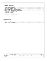
Page 2: ...Hopping 2 of 10 1 TABLE OF CONTENTS 1 TABLE OF CONTENTS 2 2 GENERAL DESCRIPTION 3 3 FCC COMPLIANCE NOTIFICATIONS 4 4 SETUP AND ADJUSTMENT PROCEDURE 6 5 APPROVED ANTENNA LIST 6 6 LABEL PLACEMENT 6 7 MI...

Page 3: ...Hz spectrum in a transparent manner To ensure a reliable connection the radio link is fully redundant with two distinct radios Once the modules are paired they will send data through a pseudo random c...

Page 4: ...with the limits for a Class B digital device pursuant to Part 15 of the FCC Rules These limits are designed to provide reasonable protection against harmful interference in a residential installation...

Page 5: ...ce of 20mm 2 cm between the antenna and your body Do not touch or move antenna while the unit is transmitting or receiving Le Hetronic CSM2400FH r pond aux exigences d exposition aux RF des appareils...

Page 6: ...ved end control process Any settings and adjustments are preformed by factory trained personnel No final adjustments are required by the end user 5 Approved Antenna List Table 2 Approved Antenna List...

Page 7: ...ed to make use of the CSM FH radio module Figure 2 CSM FH Pin Layout Pin Description Pin Label Type FH Pin Description GND S Negative Supply Input 0 V DC Ground BATT S Positive Supply Input 2 9 5 5 V...

Page 8: ...Encryption Yes RSSI and or LQI available to all nodes Yes Channels available 200 Proprietary communications protocol Yes Circular Antenna Polarization external PCB RF connector only RHCP RF connector...

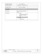
Page 9: ...0MHz RF Module with Frequency Hopping 9 of 10 Storage Temperature 40 to 105 C Operating Humidity 20 to 70 non condensing Storage Humidity 95 non condensing MECHANICAL PCB Material FR 4 Prepreg 7628 AT...

Reviews: