3085006.002 Rev. 3
7
5.
Attaching the Wiring
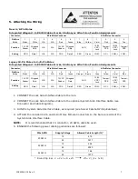
New 4-/8-Pin Molex
Integrated Wiegand: K/KS200 Cabinet Locks, ElectroLynx Wire Color/Function Assignments
Connector
8-Pin Molex Connector
4-Pin Molex Connector
Pin/Wire
Color
1
Black
2
White
3
N/A
4
N/A
5
Red
6
Green
7
Blue
8
Yellow
1
Violet
2
Pink
3
Gray
4
Tan
Function
12 VDC
Reader
Wiegand
Data
N/A
N/A
12 VDC
Reader
Wiegand
Data
LED
12/24
VDC/
Lock
Tamper/
DPS
12/24
VDC/
Lock
Tamper/
DPS
Setting
NEG
Data 1
N/A
N/A
POS
Data 0
RED
Green
COM, -
NC, +
COM, +
COM, -
Legacy 10-Pin Molex to 4-/8-Pin Molex
Integrated Wiegand: K/KS200 Cabinet Locks, ElectroLynx Wire Color/Function Assignments
Connector
8-Pin Molex Connector
4-Pin Molex Connector
Pin/Wire
Color
1
Black
2
White
3
N/A
4
N/A
5
Red
6
Green
7
Orange
8
Brown
1
Gray
2
Yellow
3
Violet
4
Blue
Function
12 VDC
Reader
Wiegand
Data
N/A
N/A
12 VDC
Reader
Wiegand
Data
LED
12/24
VDC/
Lock
Tamper/
DPS
12/24
VDC/
Lock
Tamper/
DPS
Setting
NEG
Data 1
N/A
N/A
POS
Data 0
RED
Green
COM, -
NC, +
COM, +
COM, -
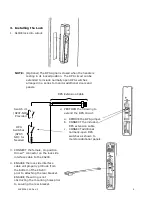
1.
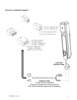
CONNECT the Lock Side Interface Cable to the lock.
2.
CONNECT the Lock Side Interface Cable to the optional System Side Interface Cable (see
Connector and Cable Diagram).
3.
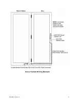
RUN the System Side Interface Cable, as required (see Server Cabinet Wiring Example).
4.
ATTACH the included 4-Pin and 8-Pin Molex Female Connectors to the bare wire side of the
System Side Interface Cable.
NOTE:
It is recommended that 10-conductor, 24 AWG, cable be used.
5.
ENSURE the following power cabling guidelines are followed:
Wire AWG
Supply Voltage
Allowed Cable Length (ft.)*
20 AWG
12
419
24
3217
22 AWG
12
264
24
2023
24 AWG
12
166
24
1272
* Round trip loss. V = 2 x I x R x xft
xft = V / (2 x I x R)


