3085006.002 Rev. 3
5
3.
Installing the Lock
1.
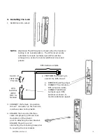
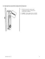
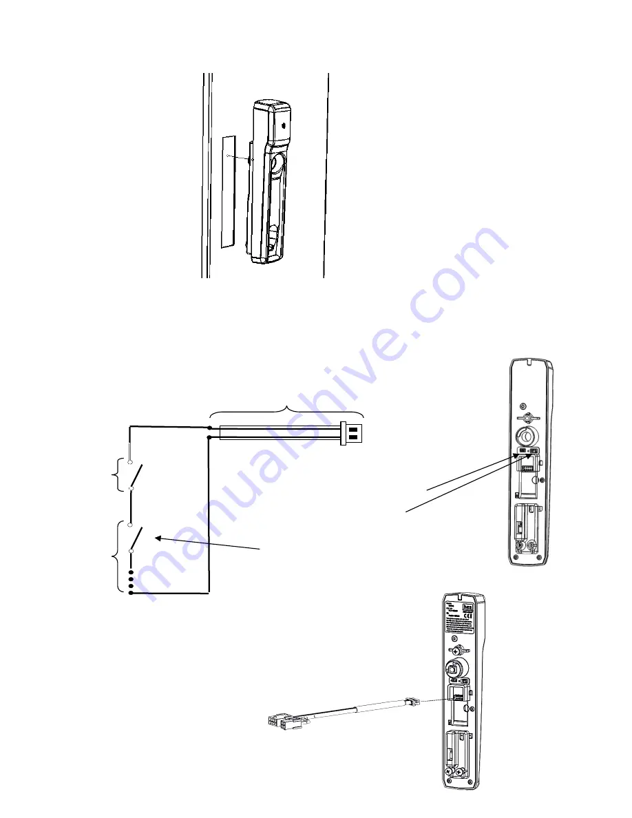
SLIDE lock into cutout.
NOTE: (Optional) The DPS signal is closed when the handle is
resting in its locked position. The DPS circuit can be
extended to include normally open DPS switches
arranged in a series to monitor additional doors and
panels.
DPS Extension Cable
DPS
Switches
(SPST-
NO): As
Needed
Optional
Switch #1
(SPST-NO):
Provided
2.
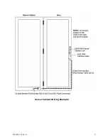
PERFORM the following to
extend the DPS Circuit.
a.
REMOVE the DPS jumper.
b.
CONNECT the included
DPS extension cable.
c.
CONNECT additional
normally-open DPS
switches as shown to
monitor additional panels.
3.
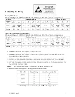
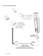
CONNECT the female, 10-position
Hirose™ connector on the lock side
interface cable to the KS200.
4.
ENSURE the lock side interface
cable will properly protrude from
the bottom of the KS200
prior to attaching the rear bracket.
ENSURE the wiring is not
obstructing the mounting holes prior
to securing the rear bracket.


