Part Number 3080006.008 Rev. 3
©2017, HES, Inc.
4
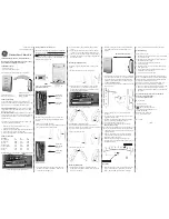
3. Installing the lock on the door
1.
Slide lock into cutout.
Plug 48V PoE RJ-45
cable into lock. Lock
will beep once and
perform self test.
3. Optional: The DPS signal is closed when the handle is
resting in its locked position. The DPS circuit can be
extended to include normally open DPS switches arranged
in a series to monitor additional doors and panels.
4. Attach rear bracket with
screws.
DPS Extension Cable
DPS
Switches
(SPST-
NO): As
Needed
Optional
Switch #1
(SPST-NO):
Provided
Extending the DPS Circuit:
A: Remove the DPS jumper
B: Connect the included DPS
extension cable
C: Connect additional normally
open DPS switches as shown
to monitor additional panels.
2. Select Power source:
(A. 24VDC Supply
<OR>
B. 48V PoE)
Connect 24VDC cable
to lock. Connect
24VDC power supply
(not provided) to
24VDC cable.
Red wire (24VDC),
black wire (Ground)
24VDC cable
A
B
5. Ensure that the lock is fully
secured and flush to the mounting
surface in order to depress
tamper switch on back of device
for correct operation.
Tamper Switch
NOTE: If the tamper switch is not
fully depressed, you will see a
flashing red light and the
device will not read cards.


