© HES 2001
4
Hanchett Entry Systems, Inc. • 2040 West Quail Ave. • Phoenix, AZ 85027 • 800-626-7590 •
www.hesinnovations.com
•
www.electricstrikes.com
FIVE YEAR LIMITED
WARRANTY
ELECTRIC STRIKE TROUBLE SHOOTING GUIDE
If the electric strike does not operate properly after
installation, the following problems may need to be corrected.
Please read carefully before calling for technical service.
Step 1.
If the electric strike does not operate properly, open the door
and re-energize the electric strike. If the electric strike operates
properly with the door held open, the lockset may be pre-loading or
binding the keeper of the electric strike.
Solution:
The horizontal relationship between the lockset and the
electric strike will have to be adjusted to eliminate the binding between
the bolt of the lock and the electric strike keeper (also See Note 2.)
Step 2.
If all mechanical problems have been eliminated without
successful electric strike operation, check the following electrical
problems:
a. Examine the power supply or transformer to verify that the output
voltage is at the listed rating.
b. Verify that the power wires leading to the electric strike are a large
enough gauge to handle the current requirements (see above).
Note: Some voltage may be lost when using smaller gauge wires
over long distances.
c. Using a multimeter: Verify that the input voltage is within the
recommended limits (+-5%).
d. Verify that all peripheral devices such as bridge rectifiers,
SMART-Pacs, buzzers, L.E.D.s etc. are properly connected.
e. Check that the switch, key pad, etc., meets the voltage requirements
for the system.
Note 1:
A quick way to determine if an electric strike is defective is to
install it in a site where another electric strike has been installed and
working properly. Another way is to use an alternative power source to
test the electric strike (i.e. a DC battery pack.)
Note 2:
If the voltage is slightly too low to operate the electric strike, a
35 volt, 220 micro-farad capacitor may be installed across the bridge
rectifier (positive to positive, negative to negative) to provide an initial
boost of power to the unit. This is also helpful to overcome slight pre-
loading conditions (as in step 1.)
F
OR ANY QUESTIONS REGARDING THIS INFORMATION
,
CALL
OUR
T
ECHNICAL
S
ERVICE
L
INE AT
1-800-626-7590
ELECTRICAL RATINGS
Continuous Duty
FOR SOLENOID
24 VDC
12 VDC
Resistance in Ohms
106.6
26.6
Amps Seated
.225
.45
C
C
AU
AU
T
T
I
I
O
O
N!
N!
Before connecting any device at
the installation site, verify input voltage and
current using a multimeter. Many power
supplies and transformers operate at higher
levels than listed. Any input voltage exceeding
5% of the solenoid rating may cause severe
damage to the unit and will void the warranty.
MINIMUM WIRE GAUGE
Solenoid Voltage
REQUIREMENTS
24 VDC
12 VDC
200 feet or less
18 gage
14 gage
200 - 300 feet
18 gage
12 gage
300 - 400 feet
16 gage
12 gage
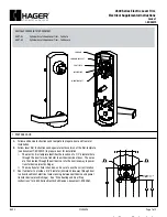
12 Volts
Figure A
White
Blue
Yellow
Orange
RIB
A
Figure B
24 Volts
RIB
White
Yellow
Blue
Blue
Orange
Orange
Part #LHA9600/004
WIRING DIAGRAM FOR 12/24 VOLTS
Caution: To prevent damage to the unit, cap all wires.
Note: 9600 is supplied as a 12 volt unit. For 24 volts see figure B.
9600 L
ATC H BOLT
M
ON ITOR
:
WIRING COLOR CODE:
White – Common
Yellow – N.O.
Orange – N.C.
Note:
Horizontal Lock
Down Screws x2