background image

Table of content 


Betriebsanleitung_firematic_20-301_Touch_Englisch V1.2 


TABLE OF CONTENT 

Seite 

1


Safety notes ................................... 5


1.1


Warnings ............................................... 6


1.2


Installation ............................................ 6


1.3


Operation and maintenance ................ 7


1.3.1


General notes ......................................... 7


1.3.2


Operation ................................................ 7


1.3.3


Maintenance ........................................... 7


2


Fuels............................................... 8


2.1


Wood chips ........................................... 8


2.2


Wood pellets ......................................... 8


3


System ........................................... 9


3.1


System design ...................................... 9


3.2


Discharge system ............................... 10


4


Example ....................................... 11


4.1


Oblique discharge system ................ 11


4.1.1


Example 1 ............................................ 11


4.1.2


Example 2 ............................................ 12


4.2


Horizontal discharge system ............ 13


4.2.1


With chute pipe ..................................... 13


4.2.2


With climbing screw .............................. 14


5


Equipment functioning ............... 15


5.1


Feeder system .................................... 15


5.2


Type of feed ........................................ 15


5.3


Combustion air control ...................... 15


5.4


Boiler operation .................................. 15


5.5


Safety devices .................................... 15


5.5.1


Safety temperature limiter .................... 15


5.6


Start-up ................................................ 16


5.7


Operating 

temperatures 

and 

impermissible temperatures ............. 16


5.7.1


Boiler temperature ................................ 16


5.7.2


Return flow temperature ....................... 16


5.7.3


Boiler temperatures that are too high ... 16


5.7.4


The flue gas temperature ..................... 17


6


Operating 

conditions 

(Combustion control) .................. 17


6.1


Heating off ........................................... 17


6.2


Ready ................................................... 17


6.3


Ignition build-up ................................. 17


6.4


Pre-ventilation ..................................... 17


6.5


Cold start ............................................. 17


6.6


Burning phase .................................... 17


6.7


Scorch phase ...................................... 17


6.8


Control phase ..................................... 17


6.9


Burnout phase .................................... 17


6.10


Burner cleaning .................................. 18


6.11


Heat exchanger cleaning ................... 18


6.12


Output control ..................................... 18


6.13


Flue gas temperature control ............ 18


6.14


Flame monitoring ............................... 18


6.15


Frost protection .................................. 18


6.16


Lambda control ................................... 18


6.17


Room discharge ................................. 18


6.18


Burnback protection device .............. 18


7


Description 

of 

the 

menu 

navigation system and settings . 19


7.1


Main menu ........................................... 19


7.2


Code entry ........................................... 20


7.3


Switching the system on and off ...... 21


7.3.1


Switching the system on ....................... 21


7.3.2


Switching the system off ....................... 21


7.4


Selecting the date and time ............... 22


7.5


Determining  values  for  the  main 
menu .................................................... 23


7.5.1


Adding display values to the main menu23


7.5.2


Deleting  display  values  from  the  main 
menu ..................................................... 24


7.6


Fault messages ................................... 25


7.7


System components .......................... 25


7.7.1


Boiler values ......................................... 26


7.7.2


Buffer values ......................................... 29


Summary of Contents for Firematic 20-60

Page 1: ...Operating instructions HERZ firematic 20 301 firematic 20 60 firematic 80 301 ...

Page 2: ...eration without a buffer storage tank with a heating load of less than 70 of the rated output manually stoked boilers must always be operated with a sufficiently dimensioned buffer storage tank if hydraulic diagrams 2 not recommended by HERZ are used and if a non prescribed fuel 3 Pellets ÖNORM M 7135 DINplus or Swiss Pellets wood chips ÖNORM M 7133 resp log wood is used Any claim to warranty serv...

Page 3: ... 16 5 7 3 Boiler temperatures that are too high 16 5 7 4 The flue gas temperature 17 6 Operating conditions Combustion control 17 6 1 Heating off 17 6 2 Ready 17 6 3 Ignition build up 17 6 4 Pre ventilation 17 6 5 Cold start 17 6 6 Burning phase 17 6 7 Scorch phase 17 6 8 Control phase 17 6 9 Burnout phase 17 6 10 Burner cleaning 18 6 11 Heat exchanger cleaning 18 6 12 Output control 18 6 13 Flue ...

Page 4: ...8 4 Information overview 41 7 8 5 Sending e mails 41 7 8 6 E mail status report 42 7 8 7 Server settings 42 8 Terms and definitions 43 8 1 Boiler values 43 8 2 Buffer values 45 8 3 Hot water tank value 46 8 4 Heating circuit 46 8 5 Time operation 49 8 6 Solar 49 9 Fault Reports and their correction51 9 1 Faults not indicated on the display Maintenance 57 9 2 Maintenance schedule Customer inspectio...

Page 5: ...intervals specified in the TGPF are to be observed When carrying out maintenance on the system or opening the control unit the power supply is to be disconnected and the generally valid safety regulations are to be heeded In the boiler room no fuels may be stored outside the system It is also not permitted for objects which are not required for the purpose of operating or carrying out maintenance ...

Page 6: ...pment unless they are supervised or instructed by a responsible person Basic safety information Due to its functionally limited electrical and mechanical characteristics with regard to usage operation and maintenance if the equipment is not able to work according to its appropriate use or improper interference occurs it may cause serious health and material damage It is therefore conditional that ...

Page 7: ...l fuel will burn independently without giving off any toxic gases provided that the chimney draught is sufficiently high Therefore the chimney must be designed and produced in accordance with DIN 4705 or EN 13384 When it is switched on again the system is to be checked in order to make sure that it is fully functional and the safe operation of the whole system must be guaranteed If the residual ox...

Page 8: ...l as chemically untreated 4 Only if using an agitator with 3x400 Volts industrial wood waste Class B2 also includes chemically treated industrial wood waste and used wood 2 2 Wood pellets Wood pellets for non industrial use after ENplus Swisspellet DINplus or ÖNORM M 7135 resp pellets after EN14961 2 according to following specifications Property class A1 The maximum permissible fines content in t...

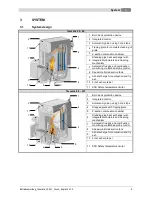
Page 9: ...peed controlled suction fans 9 Ash discharge for combustion and fly ash 10 Front ash container 11 STB Safety temperature limiter firematic 80 301 1 Burn back protection device 2 Integrated control 3 Automatic ignition using hot air fans 4 Stepped grate with Tipping grate 5 2 section combustion chamber 6 Standing pipe heat exchanger with integrated turbulators and cleaning mechanism 7 Automatic flu...

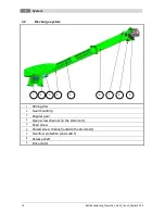
Page 10: ...glisch V1 2 3 2 Discharge system 1 Stirring disc 2 Gear mounting 3 Angular gear 4 Open screw channel in the storeroom 5 Feed screw 6 Closed screw channel outside the storeroom 7 Overflow protection end switch 8 Release shaft 9 Drive motor 1 2 3 4 5 6 7 8 9 ...

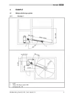
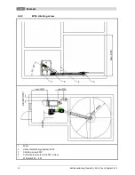
Page 11: ...Example 4 Betriebsanleitung_firematic_20 301_Touch_Englisch V1 2 11 4 EXAMPLE 4 1 Oblique discharge system 4 1 1 Example 1 1 boiler 2 Oblique discharge system 230V ati firematic 80 301 ...

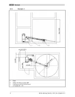
Page 12: ...4 Example 12 Betriebsanleitung_firematic_20 301_Touch_Englisch V1 2 4 1 2 Example 2 1 Boiler 2 Oblique discharge system 400V 3 Control extension for a 400V motor at firematic 80 301 ...

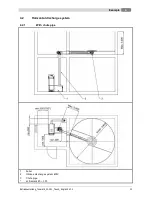
Page 13: ...Example 4 Betriebsanleitung_firematic_20 301_Touch_Englisch V1 2 13 4 2 Horizontal discharge system 4 2 1 With chute pipe 1 boiler 2 Oblique discharge system 400V 3 Chute pipe at firematic 80 301 ...

Page 14: ... 14 Betriebsanleitung_firematic_20 301_Touch_Englisch V1 2 4 2 2 With climbing screw 1 boiler 2 Horizontal discharge system 400V 3 Climbing screw 400V 4 Control extension for two 400V motors at firematic 80 301 ...

Page 15: ... weather driven optional and can be used in conjunction with a remote sensor optional from any heating circuit It is also possible to generate demand using a room thermometer The boiler can also switch on the equipment via its heat requirement The control or local data of the boiler capacity can be adjusted or changed The regulation prevents boiler temperatures falling too low as this can affect t...

Page 16: ...oiler temperature between 65 und 90 C If the return flow temperature is below 55 C some of the flue gases condense on the inside of the boiler When the boiler is started up the operating temperature from 65 to 90 C must therefore be reached as quickly as possible in order to avoid condensation The return flow temperature may also be under the permissible value at correct boiler operating temperatu...

Page 17: ...boiler temperature has reached the switch off temperature 6 3 Ignition build up In this condition the grate has been cleaned and the lambda probe pre heated 6 4 Pre ventilation This condition serves to flush the combustion chamber and the chimney with air 6 5 Cold start If the boiler room temperature is below the boiler room ignition identifying temperature standard 150 C a cold start is carried o...

Page 18: ...ced If the temperature is not reached the equipment goes back to normal output control 6 14 Flame monitoring Where the combustion values fluctuate too greatly during operation this is detected and the equipment is switched off 6 15 Frost protection When the equipment goes into frost protection then the return flow bypass pump is switched on provided that the equipment is in HEATING OFF or BURNER S...

Page 19: ...ault values 7 1 Main menu Objective To display the system values date and time as well as to branch to submenus This page will load automatically when you switch on the system using the main switch From here you can easily navigate through the settings You can select a menu option by pressing on it By touching the following button the main menu will be displayed fault messages warnings alarms will...

Page 20: ...utton you can enter the code the main menu will be displayed if you have already entered a code this will lock the field that has been changed the previous page will be displayed Menu point Main menu Code entry Navigation Screen Note Enter the corresponding code and then press OK to confirm Note The individual values shown in the following screenshots can only be changed by entering a code The cod...

Page 21: ...y been entered 7 3 2 Switching the system off Menu point Switching the system on and off Navigation Screen By touching the following button the boiler will be switched off the boiler will remain sitched on and the previous page will be displayed Note In all operating states except cold start or Ready the system will then proceed to the burnout phase If the system is switched off during a cold star...

Page 22: ...eans that the time will be updated automatically you can choose between summer and winter time you can lock the screen the main menu will be displayed Menu point Date and time NTP active Navigation Screen By touching the following button ENGLISH you can select the language to be used you can enter the name of the server you can set the time zone you can enter the update interval you can carry out ...

Page 23: ...he selected value Load scheme you can load a default diagram Delete all all the display values will be deleted BOILER 000 the boiler values which can be selected and displayed manually will be displayed BUFFER i000 the buffer values which can be selected and displayed manually will be displayed HOT WATER TANK i001 the hot water tank values which can be selected and displayed manually will be displ...

Page 24: ...values for the boiler or the individual module will be displayed Boiler must Power Back flow must etc the value will be confirmed so that it will displayed on the main menu Note The same applies to all other modules 7 5 2 Deleting display values from the main menu If the default diagram is to be deleted the procedure for doing this is as follows Menu point Main menu Code entry Navigation 111 OK Sh...

Page 25: ...ng the following button BOILER 000 the boiler values menu will be displayed see subsection 7 7 1 BUFFER i000 the buffer values menu will be displayed see subsection 7 7 2 HOT WATER TANK i001 the hot water tank values menu will be displayed see subsection 7 7 3 HC i002 the heating circuit 1 values menu will be displayed see subsection 7 7 4 TIME MODE 000 the time mode values menu will be displayed ...

Page 26: ...t can be activated the next page of the boiler values will be displayed the overview of system components will be displayed again Boiler status 1 Menu point System components Boiler values Navigation BOILER 000 navigate 1 page to the right Screen Note The individual terms are explained in the section 8 1 entitled terms and definitions Boiler status 2 Menu point System components Boiler values Navi...

Page 27: ...in the section 8 1 entitled terms and definitions Boiler settings Menu point System components Boiler values Navigation BOILER 000 navigate 4 pages to the right Screen By touching the following button 1 you can set the residual heat temperature 2 you can set the control hysteresis 3 you can set the minimum requirement 4 you can set the power maximum 5 you can set the fuel Note The individual terms...

Page 28: ...navigate 6 pages to the right Screen By touching the following button If an element for example lambda heating is active the indicator lamp will light up green Boiler outputs 3 Menu point System components Boiler values Navigation BOILER 000 navigate 7 pages to the right Screen By touching the following button If an element for example back flow pump is active the indicator lamp will light up gree...

Page 29: ... System components Boiler values Navigation BOILER 000 navigate 10 pages to the right Screen By touching the following button The individual terms are explained in the section 8 1 entitled terms and definitions 7 7 2 Buffer values Menu point System components Buffer values Navigation BUFFER i000 Screen By touching the following button informations of the module are shown you can activate the aggre...

Page 30: ...ponents Buffer values Navigation BUFFER i000 navigate 2 pages to the right Screen Note The individual terms are explained in the section 8 2 entitled terms and definitions Buffer settings 1 Menu point System components Buffer values Navigation BUFFER i000 navigate 3 pages to the right Screen By touching the following button 1 you can set the target winter must temperature 2 you can set the target ...

Page 31: ... fastrun heating is active the term fastrun heating in the buffer status II and the terms fastrun heating OPEN and CLOSED in the Buffer Agg Test are shown 3 you can select the outside temperature sensor 4 you can enter the temperature for the balancing outside sensor 5 you can activate the Buffer re layering Buffer Aggregate Test Menu point System components Buffer values Navigation BUFFER i000 na...

Page 32: ...alues Navigation HOT WATER TANK i001 navigate 1 page to the right Screen Note The individual terms are explained in the section 8 3 entitled terms and definitions Hot water tank settings Menu point System components Hot water tank values Navigation HOT WATER TANK i001 navigate 2 pages to the right Screen By touching the following button 1 you can set the must temperature 2 you can set the minimum ...

Page 33: ...copied into the other days of the week Hot water tank aggregate test Menu point System components Hot water tank values Navigation HOT WATER TANK i001 navigate 4 pages to the right Screen Note If the element Hot water tank pump is active the indicator lamp will light up green 7 7 4 Heating circuit Menu point System components heating circuit Navigation HC i002 Screen By touching the following butt...

Page 34: ...ff the heating circuit 2 you can select the operation mode 3 you can select the remote control number 4 the balancing for the room sensor can be entered only visible when a remote control number is selected 5 the kneeling barrier over room temperature can be activated Heating circuit parameter 1 Menu point System components heating circuit Navigation HC i002 navigate 4 pages to the right Screen By...

Page 35: ...neeling barrier Heat curve Menu point System components heating circuit Navigation HC i002 navigate 6 pages to the right Screen Common system temperatures are FF RF in C Old standard 90 70 New standard 75 65 Low temperature 70 50 70 55 Combustion value 60 45 55 45 Floor heating 35 30 Heat curve settings Menu point System components heating circuit Navigation HC i002 navigate 7 pages to the right S...

Page 36: ...it aggregate test Menu point System components heat circ Navigation HC i002 navigate 9 pages to the right Screen By touching the following button you can activate the aggregate Test 7 7 5 Time mode Menu point System components time mode Navigation TIME MODE Screen By touching the following button Time 1 you can choose between 3 times you can enter the period of time for each day of the week indivi...

Page 37: ...he aggregate test informations of the modules are shown Solar Status 1 Menu point Systemkomponenten Solar Navigation SOLAR i004 navigate 1 page to the right Screen Note The individual terms are explained in the section 8 6 entitled terms and definitions Solar Status 2 Menu point System components Solar Navigation SOLAR i004 navigate 2 pages to the right Screen Note The individual terms are explain...

Page 38: ...u can set the minimum rotation speed 6 you can enter the must value 7 you can enter the temperature for the control difference Solar settings 2 Menu point System components Solar Navigation SOLAR i004 navigate 4 pages to the right Screen By touching the following button 1 you can set the pump trigger 2 you can set the tank must temperature 3 you can set the difference temperature 4 you can set the...

Page 39: ...ion such as software version operating system number will be displayed you can send messages by e mail you can set mail times when an e mail is to be sent the mail server settings will be displayed 7 8 1 Network configuration Menu point Menu settings Network configuration Navigation 111 OK Screen By touching the following button you can set the IP address you can set the subnet screen form you can...

Page 40: ...u can set the port number you can set the timeout you can set the RX TX Buffer in Byte you can set the maximum values Accept changes the changes are accepted the network configuration page will be displayed again 7 8 3 Screensaver Menu point Menu settings Screensaver Navigation 111 OK Screen By touching the following button 1 you can activate the screensaver 2 you can set the period of time after ...

Page 41: ...n enter the subject sending will be activated the list of menu settings will be displayed Receiver list Menu point Menu settings Mail settings Navigation 111 OK Receiver list Screen By touching the following button you can enter the e mail address of a recipient you can add the e mail address of the recipient to the list of recipients you can delete the e mail address of the recipient from the lis...

Page 42: ...int Menu settings Mail settings Navigation 111 OK Screen By touching the following button Test mail send you can set the e mail to the recipient 7 8 6 E mail status report Menu point Menu settings Mail settings Navigation 111 OK Screen By touching the following button 1 you can enter the number of times max 5 times 2 6 you can enter the individual times the list of menu settings will be displayed ...

Page 43: ...o material will be fed in O2 Display value Display of O2 values CO2 Display value Display of CO2 values Residual heat temperature Setting value Temperature indicating how far the boiler may be emptied for refilling or when the return flow booster pump will be switched on Control hysteresis Setting value Temperature indicating the boiler regulation limit above the required temperature Minimum requi...

Page 44: ...ol Display value Indication of the state of the output temperature control if active indicator lamp will light up green Sum annoyance Display value Indication of the state of the sum annoyance if active indicator lamp will light up green Operating alarm unit Display value Indication of the state of the alarm unit if active indicator lamp will light up green Grate closed Display value Indication of...

Page 45: ...ffer bottom temperature Display value Buffer bottom temperature Switching temperature Display value Outside temperature setting above which the change over between summer and winter operation will take place Outside temperature Display value Outside temperature in C Required temperature Display value Indication of the temperature required for modules HC water heater Buffer loading pump Display val...

Page 46: ... Maximum time for loading the hot water tank Legio temperatura Setting value Hot water tank temperature setting the water heater will be heated to this temperature in order to kill bacteria Circulation pump Display value Activation of the circulation pump Loading valve Display value Indicator lamp 8 4 Heating circuit Term Display set value Description Flow temperature Display value Flow temperatur...

Page 47: ...ture Example Room must temperature 22 C Actual room temperature 20 C Room influence 5 Difference between Room must temperature Actual room temperature 2 K This difference is multiplied by the room influence 2 K x 5 10 K I e 10 K will be added to the calculated feed flow temperature If the actual room temperature is higher than the target room temperature the calculated value will be deducted Kneel...

Page 48: ... up Setting range from 10 to 10 Day middle switching temperature Setting value The day middle switching temperature already mentioned works as an average value generator This means that from when it is first switched on an internal average temperature generator of the external temperature starts up This runs continuously in the background Should the daytime average target temperature that you have...

Page 49: ...ircuit mixer if active indicator lamp will light up green and mixer will be closed 8 5 Time operation Term Display set value Description Time requirement Setting value Is intended for the situation where no heating circuits are connected and the system is only being used to produce energy 8 6 Solar Term Display set value Description Collector flow temperature Display value Measured value Collector...

Page 50: ...vation of the collector pump Tank 1 must temperature Setting value Must value of Tank 1 temperature Difference 1 Setting value Difference between collector and Tank 1 Tank 1 max temperature Setting value Maximum value of Tank 1 temperature Collector pump Display value Indication of the state of the collector pump if active indicator lamp will light up green ...

Page 51: ...ialist installer FAULT 4 F STOKER SENSOR Stoker sensor defective or break in sensor cable or plug not inserted correctly Contact your specialist installer FAULT 5 F BOILER OUTSIDE TEMP SENSOR Boiler outside temp sensor defective or break in sensor cable or plug not inserted correctly Contact your specialist installer FAULT 6 F BUFFER SENSOR TOP Buffer sensor top defective or break in sensor cable ...

Page 52: ...18 F SENSOR COLLECTOR BACK FLOW Collector back flow sensor defective or break in sensor cable or plug not inserted correctly Contact your specialist installer FAULT 19 F SENSOR SOLAR TANK 1 Solar tank sensor 1 defective or break in sensor cable or plug not inserted correctly Contact your specialist installer FAULT 20 F SENSOR SOLAR TANK Solar tank sensor 2 defective or break in sensor cable or plu...

Page 53: ... compensator Frost protection function activated Display only no action required FAULT 34 F ANTIBLOCKING BACK FLOW Blocking protection activated for return flow pump Return flow pump triggered for 10 s approx Display only no action required FAULT 35 F BOILER LOADING Boiler setpoint could not be reached in the specified time Adjust time Control the hydraulic FAULT 37 F HEATING OFF The system is on ...

Page 54: ...F CHECK DATA MODUL A module parameter is not in the specified range Control the module parameter FAULT 57 F CHECK DATA BOILER A boiler parameter is not in the specified range Control the boiler parameter FAULT 58 F MAINTENANCE Contact your specialist installer FAULT 59 F INSERTION IN ACTION Feed screw temperature too high when in operation Contact your specialist installer FAULT 60 F INSERTION NOT...

Page 55: ...ASCHENBEH VOLL Ash pans are full and need to be emptied Empty the ash pans FAULT 75 F FUEL FAULT 76 Error fire out has occured within 2h again see error 66 F ADDITIONAL INPUT Additional input for example CO detector has been activated Check system pressure FAULT 77 F NIVEAU LEVEL Niveau sensor has been activated FAULT 78 F BARRIER LEVEL Sensor in the insertion screw channel reports that no materia...

Page 56: ...oor open Contact your specialist installer FAULT 87 F NIVEAU COMPACT Niveau container at the compact container empty Control container level FAULT 88 F NIVEAU SUCTION Niveau container at the suction container empty Control container level FAULT 89 F COMB ROOM SENSOR Endswitch of the combustion room door has been activated Combustion chamber door is open Close combustion chamber door Control endswi...

Page 57: ...fly ash container Clean the heat exchangers Desired operating temperature is not reached Fuel of inferior quality Previous boiler output higher than current boiler output Fuel level too low Replace fuel if necessary Install a larger boiler Increase fuel level Ash is emitted from the chimney Fly ash container full Fuel contains excessive fines or super fines Fan speeds too high Chimney draught too ...

Page 58: ...weeks a Operation of the controller a Switch the controller on and off make sure that it is working properly b Fault messages b Check Faults must also be displayed c Combustion air fan induced draught fans c Check Fans must be work properly when the boiler is in operation d Combustion chamber d Check the combustion chamber and clean if required e Fire extinguishers e Check Equipment must be reliab...

Page 59: ...c 301 HERZ firematic 149 Machine type Biomass furnace inclusive discharge system We declare herewith that the above described machine the above described product complies with the corresponding regulations of the following EC Directives The conformity is verified by the complete compliance with the following standards EU directive Standard 2006 95 EG Low tension units decree EN 60335 1 A2 06 EN 60...

Page 60: ...ischarge system 11 Operating conditions Burnback protection device RSE 18 Burner cleaning 18 Burning phase 17 Burnout phase 17 Cold start 17 Control phase 17 Flame monitoring 18 Flue gas temperature control 18 Frost protection 18 Heat exchanger cleaning 18 Heating off 17 Ignition build up 17 Lambda control 18 Output control 18 Pre ventilation 17 Ready 17 Room discharge 18 Scorch phase 17 Operating...

Page 61: ...11 Betriebsanleitung_firematic_20 301_Touch_Englisch V1 2 61 T Table of content 3 Terms and definitions Buffer values 45 Heating circuit 46 Solar 49 Time operation 49 Terms and definitions 43 Time mode 36 W Warnings 6 ...

Page 62: ...12 Notes 62 Betriebsanleitung_firematic_20 301_Touch_Englisch V1 2 12 NOTES ...

Page 63: ...Notes 12 Betriebsanleitung_firematic_20 301_Touch_Englisch V1 2 63 ...

Page 64: ...ummer V 1 2 Herz Energietechnik GmbH Herzstraße 1 7423 Pinkafeld 43 3357 42 84 0 0 43 3357 42 84 0 190 office energie herz eu Deutschland Germany Herz Armaturen GmbH Fabrikstraße 76 D 71522 Backnang 49 7191 9021 0 49 7191 9021 79 verkauf herz armaturen de ...

Reviews: