background image

– MOUNTING THE STOVE                                    


We strongly recommend professionals install the stove for you. 
To unpack your stove, remove the screws and staples that fasten it to the pallet. Your stove will 
weigh more than 100 Kg. Take your stove out of the pallet carefully and with the necessary help 
and place it where you intend to install it. 
Once  it  has  been  installed,  ensure  that  it  is  stable.  If  necessary,  the  stove  can  be  regulated 
levelling screws.  
Connect the stove to the chimney ensuring the union is perfectly sealed. Please read the chimney 
installation chapter in the installation manual for the engineer. 
Keep the packaging elements of your stove until you have ensured it works properly. 
Recycle packaging materials, such as cardboard

, wood, plastic… 

Do not use the packaging materials to light your stove.  
 
CHANGING THE SMOKE OUTLET TO THE REAR ONE 
To  change  the  smoke  extract  to  the  rear  one,  please  follow  the 
following steps: 
Note that the rear protector panel of your stove has a round cut out 
piece held in place at three points.  
Push  and  pull  the  top  of  the  circle  several  times,  gently,  outwards 
and inwards. The piece will come off easily, leaving a smoke outlet 
on  the  rear  side.  There  is  no  need  to  dismantle  this  piece.  If 
necessary, file down the burr remaining in the open hole. 
Open  the  stove  door  and  dismantle  the  deflector  dolly  and  the 
deflector  itself,  and  remove  them  from  the  stove.  The  two  smoke 
outlets shall be in full view.  
 

Dismantle  the  smoke  cover  from  the  rear  by 
unscrewing the two screws and the washers that fasten it. 
Then, remove the screws and washers that fasten the flue collar of 
the smoke outlet from the upper side. 
Place the flue collar of the smoke outlet on the rear side, ensuring 
the seal is in its correct position and fasten it with the corresponding 
screws and washers.  
Place the cover on the upper part of the stove ensuring the seal is 
in  its  correct  position  and  fasten  it  with  the  screws  and  washers. 
Note  that  the  top  only  has  one  possible  position  according  to  the 
form of the upper part of the stove.  


FIG.3 

Summary of Contents for E-30 XS

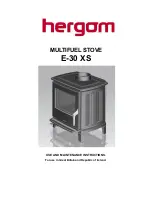
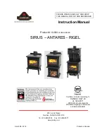
Page 1: ...MULTIFUEL STOVE E 30 XS USE AND MAINTENANCE INSTRUCTIONS Foruse in Great Britainand Republic of Ireland...

Page 2: ......

Page 3: ...or warning Industrias Herg m S A domiciled in Soto de la Marina Cantabria Spain offers a TWO YEAR warranty on its products The geographical coverage of the said warranty only includes the countries in...

Page 4: ...ed in the same room as the stove because this can cause the stove to emit fumes into the room Asbestos This stove contains no asbestos If there is a possibility of disturbing any asbestos in the coars...

Page 5: ...ash box behind the door to the fire chamber Grate shaker for use with coal also behind the door Air inlet from the exterior or independent living room through the rear connector at the back of the st...

Page 6: ...that the rear protector panel of your stove has a round cut out piece held in place at three points Push and pull the top of the circle several times gently outwards and inwards The piece will come o...

Page 7: ...ning firewood it is advisable to close it completely once the fire has been lit This valve is normally used for regulating the coal combustion Primary air valve Glass cleaning Open the valve to its fu...

Page 8: ...etroleum derivatives This will render the product warranty void For supplies of adequate coal supplies please contact your stove dealer CONSUMPTION The consumption for the stove according to the tests...

Page 9: ...onvenience control combustion and never overheat the heater INDUSTRIAS HERG M S A may not be held liable for the deterioration of the stove s enamel if these instructions are not followed 6 CLEANING M...

Page 10: ...ial supervision as well as pets away from the fireplace when it is in use Make sure that children or other people who are not familiar with how the device works are supervised by responsible people wh...

Page 11: ...he minimum diameter and the maximum length of the pipe to be connected 8 STROUBLE SHOOTING 1 Fire Will Not Burn check a the air inlet is not obstructed in any way b that chimney and flue ways are clea...

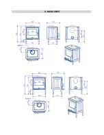
Page 12: ...9 MEASURES...

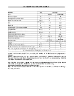
Page 13: ...meter of outer air inlet connection pipe mm 80 80 Maximum length of outer air inlet connection pipe 1 m 8 8 1 For distances exceeding 8 m consult please In the case of other dimensions consult your De...

Page 14: ...11 EXPLODED VIEW...

Page 15: ...the said repairs may cause POS CODIGO NOMBRE 1 9920201 CONJUNTO MANDO CIERRE PUERTA HOGAR 2 9920560 CONJUNTO PUERTA HOGAR 3 9920197 CONJUNTO BISAGRA PUERTA HOGAR 4 9920561 CONJUNTO CRISTAL 5 9920562...

Page 16: ...DATA PLATE...

Page 17: ......

Page 18: ...NOTES...

Page 19: ......

Page 20: ...INDUSTRIAS HERGOM S A SOTO DE LA MARINA CANTABRIA Apdo de correos 208 SANTANDER Tel 0034 942 587 000 E mail hergom hergom com www hergom com C03602 Versi n 2...

Reviews: