


Installation and Operation Manual
HL-10P(LV) Installation Manual Ver 1.0
4
Part Number MAN-000024
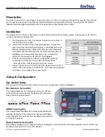
BinTrac Indicator Setup
The BinTrac Indicator must be set up for peripheral devices. Access the SETUP menu on the BinTrac Indicator by
pressing and holding the BIN key until
appears, then release. If the display changes to
, press the
UPPER
key once to return to
.
The Bin LEDs indicate configuration options as being enabled (solid on) or disabled (flashing).
Bin A
– Configures BinTrac Monitor as a Remote Display.
Bin B
– Enable ASCII Serial Communications Command Set
Bin C
– Enable Weight Broadcast.
Bin D
– Enable communications to peripheral devices.
This must be enabled when BinTrac Indicator is connected to the HouseLink HL-10P(LV).
1. Press the BIN key to select the desired configuration option.
2. Use the UPPER
or LOWER
keys to enable or disable options.
Operation
Status LEDs
The LED will flash three different ways dependent upon how the unit is operating.
SLOW FLASH
– This indicates the unit is communicating and operating normally.
FAST FLASH
– This means the unit is in Test mode.
STEADY ON
– This indicates the unit is not communicating but has power.
NO LIGHT
– The unit doesn’t have an adequate power source.
Testing & Calibration
Once the unit is wired and the dip switches are set up correctly, the unit can be put into one of five test modes. These
modes are useful when setting up and testing with the house controls.
Please note: Due to increased filtering effects on house controllers, for best calibration results wait thirty
seconds after each button press on the HL-10P so weights can stabilize before proceeding further in the
calibration process.
Test 1
– Press the Test button on the board once and the unit will output -0.5 mV/V.
Test 2
– Press the Test button on the board twice and the unit will output 0 mV/V.
Test 3
– Press the Test button on the board three times and the unit will output 2 mV/V.
Test 4
– Press the Test button on the board four times and the unit will output 3 mV/V.
Test 5
– Press the Test button on the board five times and the unit will output 4.5 mV/V.
Pressing the test button a sixth time will return the unit to normal operations. If the unit is left in test mode, it will
automatically return to normal operation mode after five minutes.
*For calibrating the HouseLink HL-10P(LV) with a
Maximus-Systems
control, please refer to instructions in Addendum A.