herdstar BinTrac HouseLINK HL-10P Installation And Operation Manual Download Page 3

Installation and Operation Manual 

HL-10P(LV) Installation Manual Ver 1.0


3


Part Number MAN-000024


Description 

The House Link HL-10P Low Voltage (LV) provides a 2mV/V or 3mV/V output proportional to the weight of the selected 
bin. The device will connect to the BinTrac Indicator BINS port in parallel with the Smart Summing Box. The BinTrac 
Indicator transmits digital weight data which is converted to a proportionate millivolt output. 

Installation 

The HouseLink HL-10P(LV) is designed


to be used with the BinTrac Bin Weighing system. One HouseLink HL-10P(LV) 

can be connected per displayed bin. 

1.  The HouseLink HL-10P(LV) should be mounted no more than 10 

feet from the house control.


2.  Using a two-conductor cable (ordered separately), connect the 

green wire from the Smart Summing Box (or the BINS port on the 
BinTrac Indicator) to the +COM (OUT) terminal in the HouseLink 
HL-10P(LV) and the white wire from the Smart Summing Box (or 
the BINS port on the BinTrac Indicator) to the  -COM (OUT) 
terminal in the HouseLink HL-10P(LV). See 

Figure 1

.  

3.  Connect the HouseLink HL-10P(LV) to the house control by 

connecting the +EXC (IN) to the + EXC terminal and the 
 

–EXC (IN) to the –EXC terminal of the house control. 

4.  Finally, connect the +mV/V (OUT) from the HouseLink HL-10P(LV) 

to the + SIG of the house control and the 

–mV/V from the HouseLink  

HL-10P(LV) to the 

–SIG of the house control. 

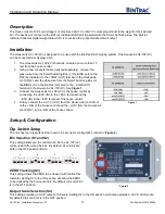
Setup & Configuration 

Dip Switch Setup 

The unit has four dip switches that need to be set up for configuration (circled in 

Figure 2

). 

Bin Selection (S1 and S2) 

This setting allows you to control which bin the HL-10P(LV) 
will send data from (see below).  By default, S1 and S2 are 
both in the OFF position (Bin A).  


ZERO Tracking (S3) 

This setting allows the ZERO to be tracked with the BinTrac 
Indicator. Setting S3 to the ON position will allow the ZERO 
to be tracked by the house controls. By default, dip switch S3 
is in the OFF position. 

Output Scale Selection (S4) 

This setting provides a 3mV/V output at full scale. Setting S4 to the ON position will instead provide a 2mV/V at full scale. 
By default, dip switch S4 is in the OFF position. 

A

B

C

D

                      Figure 1 

Figure 2 

Figure 1 

Summary of Contents for BinTrac HouseLINK HL-10P

Page 1: ...Installation and Operation Manual HouseLink HL 10P LV 12 5 2022 Installation and Operation Manual HouseLink HL 10P LV ...

Page 2: ...etup 3 BinTrac Indicator Setup 4 Operation 4 Status LEDs 4 Testing Calibration 4 Output Specification 5 Operational Specifications 6 Addendum A 7 Addendum A Wiring Diagram 8 is a registered trademark of HerdStar LLC Copyright 2022 HerdStar LLC All rights reserved Printed in the USA 1400 Madison Avenue Suite 504 Mankato MN 56001 PH 507 344 8005 FAX 507 344 8009 www herdstar com ...

Page 3: ...rac Indicator to the COM OUT terminal in the HouseLink HL 10P LV See Figure 1 3 Connect the HouseLink HL 10P LV to the house control by connecting the EXC IN to the EXC terminal and the EXC IN to the EXC terminal of the house control 4 Finally connect the mV V OUT from the HouseLink HL 10P LV to the SIG of the house control and the mV V from the HouseLink HL 10P LV to the SIG of the house control ...

Page 4: ...This indicates the unit is not communicating but has power NO LIGHT The unit doesn t have an adequate power source Testing Calibration Once the unit is wired and the dip switches are set up correctly the unit can be put into one of five test modes These modes are useful when setting up and testing with the house controls Please note Due to increased filtering effects on house controllers for best ...

Page 5: ... Total Weight 1 00 75 1 00 50 0 00 0 1 00 50 2 00 100 3 00 150 4 00 200 4 50 225 4 50 250 mV V of Total Weight 1 00 75 1 00 33 3 0 00 0 1 00 33 3 2 00 66 6 3 00 100 4 00 133 33 4 50 150 4 50 175 1 00 1 00 0 00 1 00 2 00 3 00 4 00 4 50 4 50 2 00 1 00 0 00 1 00 2 00 3 00 4 00 5 00 100 0 100 200 300 mV V Output of Total Weight 2mV V Output mV V 1 00 1 00 0 00 1 00 2 00 3 00 4 00 4 50 4 50 2 00 1 00 0...

Page 6: ...rovals N A Wiring Type Screw terminal block Power Requirements 2 25 VDC 2 75 VDC 70 mA max Output Signal Type Simulates 3mV V 360 ohm load cell Maximum Output Signal Range 1 0 mV V to 4 5 mV V Default Output Value 1 0 mV V Maximum Load Capacitance No limit Zero Accuracy 35 mV V Span Accuracy 0 2 of reading Linearity Error 0 02 of full scale Span Temperature Stability 35 ppm C Output Signal Resolut...

Page 7: ...t up for peripheral devices Follow the procedure shown in the HouseLink HL 10P LV Installation and User Guide 9 Calibrate the Maximus control using the calibration method for empty and full weight and using the HouseLink HL 10P LV test mode to output an empty and full weight simulated weight reading Please note Due to increased filtering effects on house controllers for best calibration results wa...

Page 8: ...Installation and Operation Manual HL 10P LV Installation Manual Ver 1 0 8 Part Number MAN 000024 Addendum A Wiring Diagram ...

Reviews: