HERAEUS
Instruction and Operating Manual
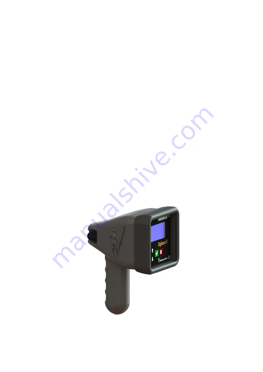
Temperature Measuring Unit
Digilance V
Document Version: 1.01
Date of Issue: 26 November 2018
Original instructions
Page 1: ...HERAEUS Instruction and Operating Manual Temperature Measuring Unit Digilance V Document Version 1 01 Date of Issue 26 November 2018 Original instructions...
Page 2: ......
Page 3: ...Electro Nite This manual is copyrighted by Heraeus Electro Nite No part of this document may be reproduced transmitted transcribed stored in any retrieval system or translated into any language by any...
Page 4: ...Page 2 of 21 Digilance V 26 November 2018 File name Digilance V_1 01 Version 1 01...
Page 5: ...he Instrument 9 4 Standard Operation 10 4 1 First Use 10 4 2 Lance Installation 11 4 2 1 TC Wire Color Codes 11 4 3 Performing Measurements 12 4 3 1 Measurement Evaluation 12 4 4 Measurement History 1...
Page 6: ...rating personnel who have been trained to work with automation equipment instruments or electronic devices and are conversant with the content of the manual in as far as it is connected with the actua...
Page 7: ...Nite instruments placed on the market after 1 July 2006 do not contain materials prohibited according to the RoHS directive Affected parts and components are identified and adapted to the statutory re...
Page 8: ...ep the battery out of the reach of children Never use a battery that appears to have suffered abuse Battery must be charged in appropriate charger only Never use a modified or damaged charger Store ba...
Page 9: ...15 of the FCC Rules These limits are designed to provide reasonable protection against harmful interference in a residential installation This equipment generates uses and can radiate radio frequency...
Page 10: ...x which enables communication and data storage possibilities using Heraeus Electro Nite software The instrument also stores measurement results internally for downloading via the wireless interface 1...
Page 11: ...ies ensure that the conductive packing does not touch or short circuit the battery connections if necessary cover the connections with insulating tape or material 3 3 Packaging the instrument Since th...
Page 12: ...n Login o Instrument Info o Battery Info o Wireless Info optional Prior to using the instrument it is recommended to confirm the following instrument settings See Section Instrument Configuration Conf...
Page 13: ...ument Assembly according to the diagram Conductive Shielding of the Thermocouple Extension Cable may not extending into the instrument housing This could create a short circuit of the electronic compo...
Page 14: ...e Stop Difference 2 1 3 See Measurement Mode MULTI End Signal Duration 2 1 4 Controls the length of time that the Buzzer and Red Light will signal the end of the measurement Window 2 2 Temperature Res...
Page 15: ...ible to enter Heat Numbers from the Main Measurement Display Set Place1 8 3 2 1 8 Configure the List of Eight Measurement Place Names Alphanumeric 10 digits Display Place 3 2 9 If set to Yes it is pos...
Page 16: ...ed by pressing Charging Process Display Message LED Status Setup Charging Yellow Blinking Displayed when the Power Supply is initially connected to the device Charging Green Blinking Charge Level Indi...
Page 17: ...ion Awake Time 4 1 Determines how long the instrument will remain awake after activity Set the values to ALWAYS to manually power the instrument On and Off Motion Sensitivity 4 2 Controls the accelero...
Page 18: ...ITS90 1 3 L R Temperature Unit C F C F 1 4 Time 1 4 1 L R Time Format AM PM 24hr 24hr AM PM 1 4 2 Set Time 1 5 Date 1 5 1 L R Date Format DD MM YY MM DD YY DD MM YY MM DD YY 1 5 2 Set Date 2 Evaluatio...
Page 19: ...erial Number 6 Service 6 1 Device Status Hardware Status Screen 6 2 Load Standard Parameters Yes No No No 6 3 Reset All Parameters Yes No No No 6 4 Temperature Offset 5 0 C to 5 0 C 0 C 0 C 7 A Admini...
Page 20: ...tarting maintenance or installation make sure that you have sufficient protection against ESD Electronic devices can be destroyed by voltage and energy levels that are far below the level perceptible...
Page 21: ...ging limit 0 C The charge current is used to heat the pack charging will initiate when the temperature is above the minimum limit Battery too hot Battery is too hot for charging Battery Temperature is...
Page 22: ...s IPTS 48 IPTS 68 ITS 90 Thermocouple Accuracy Better than 1 C between 0 C and 50 C ambient temperature Display Resolution Configurable 1 or 0 1 Display Units C or F Data Storage 500 measurement resul...
Page 23: ...rial number Description UCS Part Number Battery Pack Replacement 31600257 Rubber Boot 31600258 Standard Housing Replacement 31600259 Wireless Housing Replacement 31600260 Antenna Assembly 31600261 The...