MOUNTING THE GUARD
1. Lift the cutting head and face it downward; align the two mounting holes in the
guard with two bolts that are preinstalled on the base of shaft. Make sure that the
internal surface of the guard faces towards the cutting head (Fig. E).
2. Lock the guard in place with the bolts and the supplied hex wrench (Fig. F).
REPLACE THE TRIMMER HEAD WITH THE 3-TEETH
BLADE
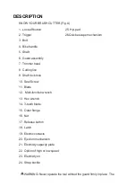
Know the trimmer head Fig. G and follow the steps as Fig. H-1 -
Fig. H-4 shown (refer to the section “line replacement”) to disassemble the trimmer
head. To mount the blade follow the steps below:
1. To mount the metal blade unit (Fig. I).
2. Remove the guard accessory by loosening the three screws with
washer (Fig.J).
The blade is shipped with a sheath. Before mounting the blade onto the brush
cutter, the sheath should be removed by undoing the
the clamp wire from the hook on the sheath (Fig. K).
NOTICE: To protect against injury, you have to wear gloves prior to any operation
with the 3-teeth blade.
Rotate the motor shaft to align the slot in the inner flange with the the
shaft-locking hole in the gear case (Fig. L).
Insert the hex wrench into the aligned holes to act as a stabilizer (Fig. M).
Mount the blade onto the motor shaft, ensuring that the surface of the blade
is flush with the surface of the inner flange bulge. Mount the outer flange and the
nut (Fig. N). Pretighten the nut in a counter
-clockwise direction by hand.
Position the gear case against a solid surface for support. With one hand hold the
brush cutter shaft and the other hand grasp the multi
-function wrench to tighten the nut following the directional arrow icon
marked on the outer flange (Fig. O).
USE OF GUARD ACCESSORY
NOTICE: When the brush cutter is equipped with a trimmer head, the guard
Summary of Contents for H36DCG120A01
Page 2: ......
Page 3: ......
Page 4: ...B ...
Page 5: ......
Page 6: ...C D ...
Page 7: ...G H3 H4 O P R4 S X2 Y ...


