23
10
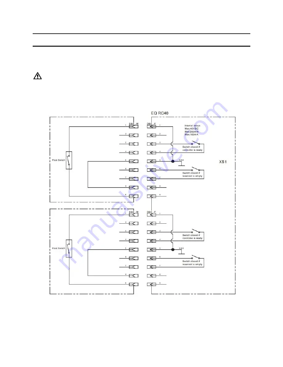
Diagrams
XS1 Start via Footswitch, additional Empty Signal and Ready Signal.
Warning!
Never connect external voltage on pin1 or pin9! NEVER short pins 3 and 4, nor 6 and 7
together, permanent board damage will result.
1
Page 1: ...1 EQ RC40 Integrated Dispenser IDH 2814025 Operating Manual...
Page 2: ...ion 5 2 1 Theory of Operation 5 2 2 Control Panel Front Back of controller 7 3 Technical Data 8 4 Installation 9 4 1 Environmental and Operating Conditions 9 4 2 Connecting the Unit 10 4 3 Filling and...
Page 3: ...s are not observed the manufacturer can assume no responsibility Do not expose the connecting cable to heat oil or sharp edges Make sure the Unit stands stable and secure Use only original equipment r...
Page 4: ...tputs 1 5 2 Low level sensor alarm provides warning for adhesive bottle replacement 1 5 3 Easy to use keypad with LCD display screen for entering values 1 5 4 Simple menu driven commands 1 5 5 Three r...
Page 5: ...with a 124mm and 2kg bottle a height of 250mm 2 Description 2 1 Theory of Operation The Loctite EQ RC40 Integrated Dispenser is connected to an external electrical and pneumatic supply The system is...
Page 6: ...l can be selected Mode 1 Digital Only Mode 2 Digital Lamp Mode 3 Digital System Stop READY Signal If the dispensing cycle is finished and unit is not dispensing a contact is closed and a READY signal...
Page 7: ...7 2 2 Control Panel Front Back of controller 2 6 14 10 11 12 13 15 9 8 7 4 5 3 1 17 20 21 23 26 16 19 22 18 24 25...
Page 8: ...Channel A OFF Output 18 Channel B ON Output 19 Channel B OFF Output 20 XS1 Channel A Master 21 XS1 Channel B 22 Air Pressure In 23 24VDC Power In 24 Silencer 25 Low Level Sensor 26 Reservoir 3 Technic...
Page 9: ...UIPMENT return it to your supplier immediately 4 1 Environmental and Operating Conditions Keep the pneumatic hose to the dispense valve as short as possible for optimum dispense control Keep product f...
Page 10: ...supplied Connect Air pressure supply to pneumatic connection 22 Connect power adapter with cord supplied to 24VDC power in connection 23 For manual operation plug the footswitch into the required 9 p...
Page 11: ...ices would become clogged and therefore ineffective Warning Before loosening the reservoir locking knobs 6 the EQ RC40 Integrated Dispenser must be depressurized pressure free When dispensing cyanoacr...
Page 12: ...essurizing valve 12 to ON position pressurize 5 Operation 5 1 Function of the Control Panel Switch 4 Switching different mode as below cycle Press the Mode button to scroll through configuration selec...
Page 13: ...start signal Timed mode only Only XS1 Channel A Master Footswitch connected The footswitch can control both output of Channel A and Channel B and start at the same time Operate one channel from a sin...
Page 14: ...ing will begin immediately and continue until the system times out Notice Channel A and Channel B outputs are active only when the OUTPUT setting is set to ON Refer to section 5 9 5 5 Run Manual Mode...
Page 15: ...witch in Run Auto mode 1 Press to select Channel A the left most digit for Channel A will start to flash 2 Press for numbering change on the flashing digit 0 01 99 99 3 Press to move the flashing digi...
Page 16: ...completed setting press to save and exit Notice Lock Out Mode ON means all setting in the system can t be change by pressing button Otherwise Setting Locked Call Supervisor will show on the display P...
Page 17: ...roduct bottle inserted into the bottle holder is pressed against the level sensor Only then the correct adjustment of the level sensor is possible Procedure to Adjust the Level Sensor 1 Turn power swi...
Page 18: ...mmended maximum idle times for different products are shown below Adhesive Maximum idle time for dispensing Systems Anaerobic 2 weeks Cyanoacrylate 1 week UV acrylate 2 weeks Acrylate 1 week Epoxy 2 w...
Page 19: ...15 defective Replace regulator LED does not light LED defect When the controller is operational the unit can be used until repaired by Henkel Service No start signal Plug on the socket XS1 20 or 21 St...
Page 20: ...duct reservoir is empty Refill product reservoir see section 4 3 Product hose not correctly connected Connect product hose correctly Dispensing valve not correctly connected or defective Check the dis...
Page 21: ...he feedline hose Remove the product bottle and insert a container with approx 0 5 liter of cleaning agent Put on the reservoir lid and uniformly tighten the reservoir locking knobs Operate the dispens...
Page 22: ...PE Teflon Lined feedline Tubing 10mtr 33ft length 142646 4 Tank Lid O ring for Reservoir 478505 5 Pressure Safety Relief Valve 360462 6 Anti Bubbler Kit 2 Adapters 2 Sleeves 478569 7 Silicone Grease 6...
Page 23: ...ams XS1 Start via Footswitch additional Empty Signal and Ready Signal Warning Never connect external voltage on pin1 or pin9 NEVER short pins 3 and 4 nor 6 and 7 together permanent board damage will r...
Page 24: ...ishable items such as fuses filters lights etc No such claim shall be allowed in respect of products which have been neglected or improperly stored transported handled installed connected operated use...
Page 25: ...EST EXTENT POSSIBLE UNDER APPLICABLE LAWS HENKEL EXPRESSLY DISCLAIMS ANY LIABILITY WHATSOEVER FOR ANY DAMAGES INCURRED DIRECTLY OR INDIRECTLY IN CONNECTION WITH THE SALE OR USE OF OR OTHERWISE IN CONN...
Page 26: ...Haw Par Technocentre SINGAPORE 149598 Henkel China Company Ltd No 928 Zhang Heng Road Zhangjiang Hi Tech Park Pudong Shanghai China 201203 Henkel Loctite Korea 8F Mapo Tower 418 Mapo dong Mapo gu Seou...