Component Replacement
42
17730-241
AR2
™
40K • 46K
SHOCK ABSORBER
NOTE
It is not necessary to replace shock absorbers in pairs if only one (1) shock absorber requires
replacement .
dISASSEMBLY
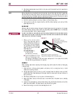
1 . Remove the lower mounting bolts, fasteners, and spacer .
2 . Remove the upper locknut and washer .
3 . Slide the shock absorber off the upper mounting bolt .
4 . Inspect the shock absorber mounting brackets and hardware for damage or wear, replace as
necessary, see the Preventive Maintenance section of this publication .
ASSEMBLY
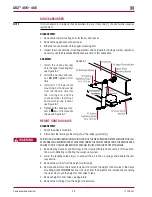
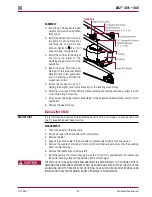
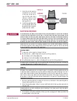
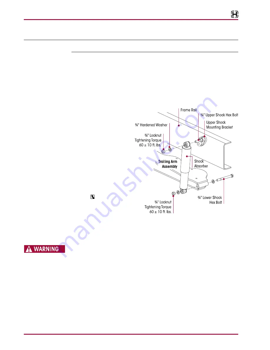
FIguRE 8‑7
1 . Install the shock absorber
onto the upper mounting bolt,
see Figure 8-7 .
2 . Install the washers and lock-
nut,
dO NOT
tighten at this
time .
3 . Install ¾" x 7¼" lower shock
mounting bolt and washer
from the inboard side into
the trailing arm and the
shock absorber . Install out-
board washer and locknut,
see Figure 8-7 .
4 . Tighten both shock eye lock-
nuts to 60 ± 10 foot pounds
torque, see Figure 8-7 .
HEIgHT CONTROL VALVE
dISASSEMBLY
1 . Chock the wheels of vehicle .
2 . Disconnect the leveling valve arm(s) from the rubber grommet(s) .
PRIOR TO AND DURING DEFLATION AND INFLATION OF THE AIR SUSPENSION SYSTEM, ENSURE THAT ALL
PERSONNEL AND EQUIPMENT ARE CLEAR FROM UNDER THE VEHICLE AND AROUND THE SERVICE AREA,
FAILURE TO DO SO CAN CAUSE SERIOUS PERSONAL INjURY, DEATH, OR PROPERTY DAMAGE .
3 . See Air Spring Cautions and Warnings in the Important Safety Notice section of this publica-
tion prior to deflating or inflating the suspension system .
4 . Lower the leveling valve arm(s) to exhaust the air in the air springs and deflate the rear
suspension .
5 . Remove the air lines from the height control valve .
6 . Remove and discard the locknut fasteners that attach the height control valve to the frame
mounting bracket .
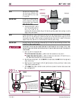
dO NOT
back out the studs from the height control valve body . Loosening
the studs may cause the height control valve to leak .
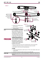
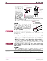
7 . Remove height control valve, see Figure 8-8 .
8 . Remove the air fittings from the height control valve .

