17730-241
39
Component Replacement
AR2
™
40K • 46K
dISASSEMBLY
1 . Remove the trailing arm assembly from the vehicle . Follow the Trailing Arm Disassembly pro-
cedure in this section .
DO NOT USE A CUTTING TORCH TO REMOVE ANY FASTENERS OR BUSHINGS . THE USE OF HEAT
ON SUSPENSION COMPONENTS WILL ADVERSELY AFFECT THE STRENGTH OF THESE PARTS . A
COMPONENT DAMAGED IN THIS MANNER CAN RESULT IN THE ADVERSE VEHICLE HANDLING AND
POSSIBLE PERSONAL INjURY OR PROPERTY DAMAGE .
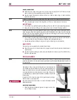
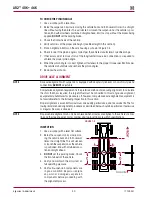
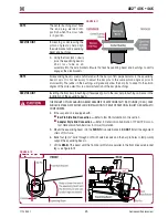
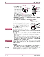
2 . Place the trailing arm assembly in a shop press with the equalizing beam center hub firmly
supported on the press bed .
3 . Install the trailing arm bushing removal tool Part no . 66086-102 (OTC 1764) centered on the
trailing arm bushing .
4 . Push directly on trailing arm bushing removal tool until the trailing arm bushing is pressed out
of the trailing arm bore .
INSpECTION
After removing the trailing arm bushings, thoroughly inspect the trailing arm bushing bores . If
damaged from trailing arm bushing removal, replace with a new trailing arm .
dO NOT
re-bush or
otherwise use trailing arm that has been damaged .
FAILURE TO REPLACE TRAILING ARM THAT HAS BEEN DAMAGED FROM BUSHING REMOVAL CAN RESULT
IN THE FAILURE OF THAT TRAILING ARM, LEADING TO ADVERSE VEHICLE HANDLING AND POSSIBLE
PERSONAL INjURY OR PROPERTY DAMAGE .
When installing rubber trailing arm bushings the following steps will minimize the chance of
damaging a new bushing:
1 . Clean the bushing bores of the trailing arm with emery cloth, removing any nicks or metal
buildup from bushing removal .
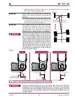
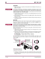
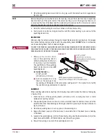
2 . Measure the inside diameter of the trailing arm’s bushing bore and the trailing arm bushing’s
outside diameter . The specification of the trailing arm’s bushing bore on a new AR2 trailing arm:
■
Inside Diameter
—
4 .365" ± 0 .004" (110 .86 mm ± 0 .10 mm)
■
Outside diameter —
4 .376"± 0 .002" (111 .15 mm ± 0 .05 mm)
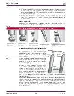
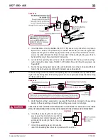
Each measurements is to be taken as the mean of any two readings at 90 degrees in the
same plane, see Figure 8-5 . If either component is not within the specified range, replace-
ment is required .
FIguRE 8‑5
3 . The trailing arm bushing bore may have a more substantial lead chamfer at one end of the
bore than the other . Take advantage of the larger chamfer by pressing in the new trailing arm
bushing from this end .

