background image

Helvar 478 8-Subnet DALI Controller: Installation and User Guide

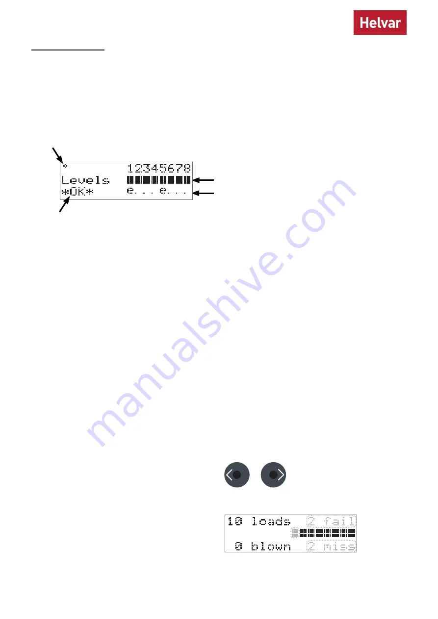
The Comms Indicator in the top left-hand corner of the main display screen indicates SDIM or DMX activity or DALI power/

activity:

• 

For SDIM/DMX it is normally off, and flashes on intermittently to indicate SDIM or DMX activity. 

• 

If DALI power is on, then the Comms Indicator is on. It flashes to indicate DALI control activity.

The Overall Health Indicator in the bottom right corner shows whether there are faults in one or more channels:

• 

If there are faults, it shows ‘Fault’ (and the Status LED flashes). 

• 

If there are no faults, it shows ‘OK’.

The main display screen appears:

• 

When the 478 is powered on.

• 

After 60 seconds of inactivity on the control panel .

• 

After exiting the control panel options.

Comms Indicator (DALI, SDIM, DMX)

Overall Health Indicator

DALI channel numbers

Channel level indicators
Emergency devices

Configuration

We recommend configuring the 478 with Designer or Toolbox.
You can also use the LCD and the control panel buttons to adjust the DALI channel outputs directly, and configure options 

for all and individual channels.
Note that the 478 is intended for controlling DALI ballasts, drivers and load interface units (except for the 490 Blinds 

Controller). Do not connect controls to the DALI outputs (DALI channels 1–8), other than Helvar compatible sensors (see 

‘Sensors’ on page 7), unless you selected Toolbox mode.
The following figure illustrates the main display screen on the LCD:

This section describes how to use the control panel buttons to adjust the DALI lighting level. During the process, the LCD 

shows a status summary of all devices that are present on each of the channels that you select: first the nonemergency 

devices, and then the emergency devices.

Adjust channel levels using the buttons

a. Adjust individual channels

From the main display screen, press the RIGHT button or 

the LEFT button.

Channel 1 will flash, and the LCD will show the following 

information about the nonemergency devices present on 

this channel: how many devices there are (top left corner), 

how many have failed (top right corner), how many lamps 

are blown (bottom left corner) and how many devices are 

missing (bottom right corner).

Use the control panel buttons to:

• 

Set DALI channel levels 

• 

Navigate the system menus to adjust module settings

Summary of Contents for Digidim DALI 478

Page 1: ...vices connected on the DALI output channel must be programmed using Helvar s Toolbox software Output levels received on the control inputs are broadcast on the corresponding output channel to provide...

Page 2: ...Contents Section Page Product description i Mounting environmental and clearance requirements 1 Installation 1 Connections 1 Configuration 4 Adjust channel levels using the buttons 5 Module Menu Opti...

Page 3: ...VAC DALI channels DALI channels Term B SC 0 V A 0 V OVR 1 2 3 4 5 6 7 8 D1 D D2 D D3 D D4 D D5 D D6 D D7 D D8 D SDIM DMX DA DA DA DA Override DALI control Mains supply AC L Live N Neutral E Earth Grou...

Page 4: ...SDIM DMX AND DALI AT THE SAME TIME iii SDIM or DMX Data Cable from previous device iv Link for Termination if unit is at end of SDIM DMX cable line Note Keep unscreened wire lengths to a minimum i SDI...

Page 5: ...signer or using the control panel buttons and the LCD Set override level for all channels or set different override levels for each channel Vin 1 5 V Ishort 1 mA 85 VAC 264 VAC 45 Hz 65 Hz OK OK OK OK...

Page 6: ...and configure options for all and individual channels Note that the 478 is intended for controlling DALI ballasts drivers and load interface units except for the 490 Blinds Controller Do not connect c...

Page 7: ...annel as required Press the RIGHT button after channel 8 to display the status information about the emergency devices on channel 1 If no emergency devices are present on that channel the main display...

Page 8: ...ther service related information Recall scene Recall a DALI scene Save as scene Save levels as a DALI scene Default scenes Reset DALI scenes to default settings Groups Group and ungroup DALI channels...

Page 9: ...the Emergencies screen Subsequently you can turn it on again with the UP button Sensors The following Helvar presence sensors can be connected to this unit as long as their firmware versions are 6 37...

Page 10: ...f channels This option is always available even when password protection is applied to other options Range scenes 1 16 Save as scene The levels which are currently active for all channels of the dimme...

Page 11: ...ride level regardless of external control signals Options Channel 1 8 ALL Override level 0 100 do not apply override level Default 100 Minimum level Set the minimum DALI lighting level that the channe...

Page 12: ...ns Channel 1 8 ALL On up button Off x down button Default x Set Toolbox mode When this mode is enabled each DALI output channel only acts as a power supply Any DALI compatible control gear or Helvar D...

Page 13: ...8 up button x down button Default x no Press OK to confirm new selection and a Done message appears The password lock will be applied after a period of 60 seconds from this message appearing Enter pas...

Page 14: ...BUS SHORTED Either DALI channel terminals are short circuited Or Too many devices have been connected to a channel and too much current is being demanded from the 478 Note The 478 also reports DALI l...

Page 15: ...Standby power No standby mode DALI power provided for DALI channels Max total losses 7 W DALI consumption 2 mA DALI system input Inputs Control DALI SDIM or DMX Override OVR Wired override input User...

Reviews: