30
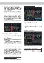
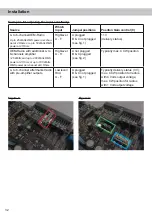
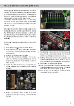
Jumper positions for extended adjustment range:
Plugged jumpers
Value range
B
(channel A - D)
Highlevel: 8 – 32 Volts
RCA
: 2 – 8 Volts
C
(channel E - H)
Highlevel: 8 – 32 Volts
RCA
: 2 – 8 Volts
Note:
If only the input channels A to D are used,
for the extended setting range it is sufficient to
remove the Load Jumper and plug it to jumper
position B.
Exact adjustment of the input sensitivity:
After you have adjusted the input load of the
amplifier to the maximum output voltage of the
signal source, follow the subsequent steps to
optimally adapt the input sensitivity by using the
Gain
control.
1. Don‘t connect any amplifiers or loud
-
speakers to the outputs of the HELIX
V EIGHT DSP MK2 during this setup.
2. Turn on the amplifier.
3. Adjust the volume of your radio to approx.
90 % of the max. volume and playback a
1 kHz full scale test tone (0 dB) via CD drive.
4. If the
Clipping LED
already lights up, you
have to reduce the input sensitivity via
Gain
control (page 26, item 9) until the LED turns
off.
5. Increase the input sensitivity by turning the
control clockwise until the LED lights up.
Now turn the control counterclockwise until
the
Clipping LED
turns off again.
For further applications please contact your
HELIX specialist dealer.
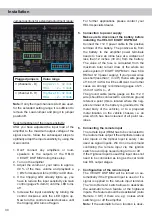
5. Connection to power supply
Make sure to disconnect the battery before
installing the HELIX V EIGHT DSP MK2!
Connect the +12 V power cable to the positive
terminal of the battery. The positive wire from
the battery to the amplifier power terminals
needs to have an inline fuse at a distance of
less than 12 inches (30 cm) from the battery.
The value of the fuse is calculated from the
maximum total current draw of the whole car
audio system (V EIGHT DSP MK2 = max. 60 A
RMS at 12 V power supply). If your power wires
are short (less than 1 m / 40”) then a wire gauge
of 16 mm² / AWG 6 will be sufficient. In all other
cases we strongly recommend gauges of 25 -
35 mm² / AWG 4 – 2!
The ground cable (same gauge as the +12 V
wire) should be connected to a common ground
reference point (this is located where the neg-
ative terminal of the battery is grounded to the
metal body of the vehicle), or to a prepared
metal location on the vehicle chassis, i.e. an
area which has been cleaned of all paint res-
idues.
6. Connecting the remote input
The remote input (
REM
) has to be connected to
the radio remote output if the amplifiers lowlevel
Line Inputs
or the
Optical Input
is solely / are
used as signal input/s. We do not recommend
controlling the remote input via the ignition
switch to avoid pop noise during turn on / off.
If the
Highlevel Input
is used this input does not
need to be connected as long as the car radio
has BTL output stages.
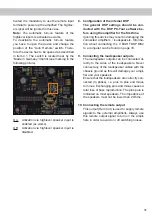
7. Configuration of the remote input
The V EIGHT DSP MK2 will be turned on au-
tomatically if the
Highlevel Input
is used or if a
signal is applied to the remote input terminal.
The “Auto Remote” switch allows to deactivate
the automatic turn-on feature of the highlevel
inputs. The feature should be deactivated (Auto
Remote = Off) if there are e.g. noises while
switching on / off the amplifier.
Note:
If the automatic turn-on function is deac-
Installation


