17
1
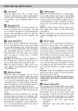
Line Input
6-channel lowlevel line input to connect signal
sources such as head units / radios. Input sensitivity
is factory-set to 4 Volts (maximum CCW position).
It is possible to vary the sensitivity between 2 and
4 Volts.
2
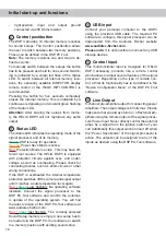
Clipping LED
This LED lights up red if one of the six lowlevel
Line
Inputs
or
Highlevel Inputs
is overdriven. The LED
has no function if the device is fed with digital input
signals. If this LED lights up reduce the input sen-
sitivity by using the control 3 (
Input Sensitivity
) until
the LED goes out.
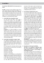
3
Input Sensitivity
This control is used to adapt the input sensitivity of
the low- and highlevel inputs to the output voltage
of the connected signal source. This is not a volume
control, it´s only for adjusting the signal processors
gain. Adjustments with this control do not affect
the optical input! The control range of the lowlevel
RCA /
Line Input
is 2 - 4 Volts and 5 - 11 Volts for
the
Highlevel Input
.
Attention:
It is mandatory to properly adapt the in-
put sensitivity of the DSP.3 to the signal source in
order to avoid damage to the signal processor.
Note:
The input sensitivity ex works is set to max.
CCW position. This is definitely the best setting for
most applications.
4
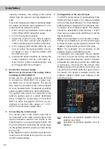
Highlevel Input
6-channel highlevel loudspeaker input to connect
the signal processor directly to loudspeaker outputs
of OEM / aftermarket radios or OEM amplifiers that
do not have any pre-amplifier outputs. Input sensi
-
tivity is factory-set to 11 Volts (maximum CCW posi
-
tion). It is possible to vary the sensitivity between 5
and 11 Volts with control 3 (
Input Sensitivity
).
Attention:
Solely use the pluggable screw-terminal
for the highlevel connector which is included in de
-
livery!
Important:
It is strictly forbidden to use the
High
level
and lowlevel
Line Input
of an individual chan
-
nel at the same time as this may cause severe dam
-
age to the lowlevel line outputs of your car radio.
Nevertheless it is possible to use the
Highlevel In
put
of one channel and the lowlevel
Line Input
of
another channel simultaneously.
5
Optical Input
Optical input in SPDIF format for connecting signal
sources with a digital audio output. The sampling
rate of this input must be between 12 and 96 kHz.
The input signal is automatically adapted to the in-
ternal sample rate. In order to control the volume of
this input, we recommend to use an optional remote
control.
Note:
This signal processor can only handle stereo
input signals and no MP3- or Dolby-coded digital
audio stream!
Note:
It is possible to use the
Optical Input
and the
Highlevel Input
or
lowlevel
Line Input
at the same
time.
6
Power Input
This input is used for connecting the signal pro-
cessor to the power supply of the vehicle and for
remote in / out. If the highlevel loudspeaker inputs
are used the remote input can be left unconnected.
The remote output is used for turning on / off ampli
-
fiers that are connected to the
Line Outputs
of the
HELIX DSP.3. Connect this remote output to the
remote inputs of your amplifier/s. This is essential
to avoid any interfering signals.
The remote output is activated automatically as
soon as the booting process of the DSP is complet-
ed. Additionally this output will be turned off during
the “Power Save Mode” or a software update pro
-
cess.
Attention:
Solely use the pluggable screw-terminal
which is included in delivery to connect the HELIX
DSP.3 to the power supply!
Important: Never use a different signal than the
remote output of the DSP to activate connected
amplifiers!
7
Ground lift switch
The signal ground of the HELIX DSP.3 is galvanically
decoupled from the power ground. In many cars this
setup is the best way to avoid alternator noise.
Nevertheless, there are use cases where it will
be necessary to directly connect input and output
ground or to tie both grounds together via a resistor.
Therefore the
Ground lift switch
has three positions:
-
center
position: input and output ground
separated.
- left position: input and output ground tied
together.
Initial start-up and functions


