14
Initial start-up and functions
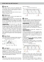
or less (one octave = doubled frequency or halved
frequency). If a subwoofer is connected we recom-
mend to use the highpass control (control 7) as vari-
able subsonic / low-frequency highpass filter or turn
it counterclockwise to 15 Hz to get a subsonic filter.
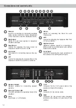
7
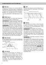
HPF
This control is used to adjust the crossover frequency
of the highpass filter from 15 Hz to 4,000 Hz. This
control is activated if the
X-Over
switch of the spe-
cific channel pair is set to HPF (highpass filter). On
channel pair C/D it is also activated in LPF / Band-
pass and its adjustment is mandatory.
8
Highlevel Input
4-channel highlevel loudspeaker input to connect
the amplifier directly to the loudspeaker outputs of
OEM / aftermarket radios that do not have any low-
level line outputs.
The
Highlevel Input
is equipped with our proprietary
ADEP circuit (Advanced Diagnostics Error Protec-
tion) which ensures that the car radio detects the
amplifier as a speaker and thus neither any function
of the radio (e.g. fader) will be deactivated nor any
error log in the CPU of the car will be created.
If this input is used the remote input (
REM
) does
not need to be connected as the amplifier will
automatically turn on once a loudspeaker signal is
applied.
Attention:
Solely use the pluggable screw-terminal
for the highlevel connector which is included in de-
livery!
Important:
It is strictly forbidden to use the
High-
level Input
and lowlevel
Line Input
at the same time.
This may cause severe damage to the lowlevel line
outputs of your car radio.
9
Level Input
These controls are used to adapt the input sensi-
tivity of the channel pairs A/B and C/D to the output
voltage of the connected signal source.
This is not a volume control, it´s only for adjusting
the amplifier gain. The control range of the RCA /
Line Input
(lowlevel) is 0.5 - 6 Volts and 1 - 14 Volts
for the
Highlevel Input
. If the
Highlevel Input
is used
in combination with a standard car radio we recom-
mend an input sensitivity of roughly 9 Volts. For this
purpose, turn the control from max. CCW position to
9 o’clock position.
10
Speaker Output
Speaker outputs of the channels A - D to connect
speaker systems. The impedance per channel
must not be lower than 2 Ohms (4 Ohms in bridged
mode).
11
Power & Protect LED
The power and protect LED indicates the operating
mode of the amplifier.
Green: The amplifier is ready for operation.
Red:
A malfunction has occurred. A malfunc-
tion may have different causes as the
HELIX D FOUR is equipped with sever-
al protection circuits. These protections
shut off the amplifier in case of overheat-
ing, over- and undervoltage, short-circuit
on loudspeakers and false connection.
Please check for connecting failures such
as short-circuits, wrong connections,
wrong adjustments and over tempera-
ture. If the amplifier does not turn on it is
defective and has to be sent to your local
authorized dealer for repair service. A de-
tailed description of the malfunction and
the purchase receipt has to be attached.
12
Fuse
The input fuses are connected in parallel and pro-
vide protection against an internal fault of the de-
vice, therefore the system must be additionally pro-
tected by a further main fuse located close to the
battery (max. distance from battery: 30 cm / 12”).
The HELIX D FOUR is equipped with 2 x 25 Am-
pere fuses.
13
+12 V
Connect the +12 V power cable to the positive ter-
minal of the battery. Recommended cross section:
min. 10 mm² / AWG 8.

