background image

16

Installation

Connection of HELIX D FOUR to the head unit / 

car radio:

Caution: 

Carrying out the following steps will re-

quire special tools and technical knowledge. In or-

der to avoid connection mistakes and / or damage, 

ask your dealer for assistance if you have any ques-

tions and follow all instructions in this manual (see 

page 11). It is recommended that this unit will be 

installed by an authorized HELIX dealer.

1.   Connecting the lowlevel line inputs

Use the correct cable (RCA / Cinch cable) to 

connect these inputs to the lowlevel line outputs 

of your car radio. It is not mandatory to use all 

lowlevel line inputs. If only two channels will be 

connected we  recommend to use the channels 

A and B and set the 

Mode Input

 switch to “2CH”. 

When all channels will be used please choose 

switch position “4CH” (see page 13, item 2; 

Mode Input

). The automatic turn-on circuit does 

not work when using the lowlevel line inputs. In 

this case the remote input (

REM

) has to be con-

nected to activate the  HELIX D FOUR.

Important:

 It is strictly forbidden to use the 

Highlevel Input

 and lowlevel 

Line Input

 at the 

same time. This may cause severe damage to 

the lowlevel line outputs of your car radio.

2.   Connecting the highlevel speaker inputs

The highlevel loudspeaker inputs can be con-

nected directly to the loudspeaker outputs of an 

OEM or aftermarket radio using appropriate ca-

bles (loudspeaker cables with 1 mm² / AWG 18 

max.). 

We recommend the following channel assign-

ment:

Channel A = Front left

Channel B = Front right

Channel C = Rear left

Channel D = Rear right

Actually it is not mandatory to use all highlevel 

speaker inputs. If only two channels will be con-

nected we recommend to use the channels A 

and B and set the 

Mode Input

 switch to “2CH”. 

When all channels will be used please choose 

switch position “4CH” (see page 13, item 2; 

Mode Input

).

Make sure that the polarity is correct. If one 

or more connections have reversed polarity it 

may affect the performance of the amplifier. If 

this input is used the remote input (

REM

) does 

not need to be connected as the amplifier will 

automatically turn on once a loudspeaker signal 

is applied.

3.  Adjustment of the input sensitivity

Attention:


It is mandatory to properly adapt 

the input sensitivity of the D FOUR to the 

signal source in order to avoid damage to 

the amplifier.

If you want to change the input sensitivity of the 

channel pairs use the two 

Level


Input 

controls 

(see page 14, item 9; 

Level Input

). The settings 

of the controls affect both the lowlevel line in-

puts (

Line   Input

) and the highlevel speaker in-

puts ( 

Highlevel Input

)! If the 

Highlevel Input

 is 

used in combination with a standard car radio 

we recommend an input sensitivity of roughly 9 

Volts. For this purpose, turn the  control from 

max. CCW position to 9 o’clock position.  

4.  Connection to power supply

Make sure to disconnect the battery before 

installing the HELIX D FOUR!

Connect the +12 V power cable to the positive 

terminal of the battery. The positive wire from 

the  battery  to  the  amplifier  power  terminals 

needs to have an inline fuse at a distance of 

less than 12 inches (30 cm) from the battery. 

The value of the fuse is calculated from the 

maximum total current draw of the whole car 

audio system (D FOUR = max. 50 A RMS at 

12 V power supply). If your power wires are 

short (less than 1 m / 40”) then a wire gauge of 

10 mm² / AWG 8 will be sufficient. In all other 

cases we strongly recommend gauges of 16 - 

25 mm² / AWG 6 – 4! 

The ground cable (same gauge as the +12 V 

wire) should be connected to a common ground 

reference point (this is located where the neg-

ative terminal of the battery is grounded to the 

metal body of the vehicle), or to a prepared met-

al location on the vehicle chassis, i.e. an area 

which has been cleaned of all paint residues.

Summary of Contents for D FOUR

Page 1: ...D FOUR 4 Kanal Class AB Verstärker 4 channel Class AB amplifier deutsch english ...

Page 2: ...heit muss der Verstärker professionell befestigt werden Dieses geschieht über Schrauben die in eine Montagefläche ein geschraubt werden die wiederum genügend Halt bieten muss Bevor Sie die Schrauben im Montagefeld befesti gen vergewissern Sie sich dass keine elektrischen Kabel und Komponenten hydraulische Bremslei tungen der Benzintank etc dahinter verborgen sind Diese könnten sonst beschädigt wer...

Page 3: ...näle C und D im Bandpass Modus 2 Mode Input Schalter zur Verteilung der Eingangssignale auf die jeweiligen Verstärkerkanäle 3 Bass Boost Regler zum Einstellen der Bassanhebung der Kanäle C und D von 0 bis 12 dB 4 Line Input Cinch Eingänge zum Anschluss eines Vorverstärkersignals 5 LPF Regler zum Einstellen des Tiefpassfilters der Kanäle C und D von 40 Hz bis 4 000 Hz 6 X Over Schalter zum Aktivier...

Page 4: ...ios die mit dem den Vorverstärkerausgang ausgängen bzw Line Out puts der Signalquelle verbunden werden können Achtung Eine gleichzeitige Verwendung der Hochpegel und Vorverstärkersignaleingänge ist nicht möglich und kann zu Schäden an Ihrem Au toradio führen 5 LPF Mit Hilfe dieses Reglers kann das Tiefpassfilter von 40 Hz bis 4 000 Hz für die Kanäle C und D einge stellt werden 6 X Over Zur Umschal...

Page 5: ...g im Fehlerspeicher des Fahrzeugs erzeugt wird Bei Verwendung dieses Eingangs schaltet der Ver stärker bei allen handelsüblichen Radios automa tisch ein so dass dieser nicht über den Remote Eingang REM eingeschaltet werden muss Achtung Verwenden Sie zum Anschluss aus schließlich den mitgelieferten Stecker mit integrier ten Schraubklemmen Achtung Eine gleichzeitige Verwendung der Hochpegel und Vorv...

Page 6: ...12 V Versorgungskabel ist am Pluspol der Batterie anzuschließen Der empfohlene Quer schnitt beträgt mindestens 10 mm 14 REM Die Remoteleitung wird mit dem Remote Ausgang Antennenanschluss des Steuergerätes Radio ver bunden Dieser ist nur aktiviert wenn das Steuer gerät eingeschaltet ist Somit wird der Verstärker mit dem Steuergerät ein und ausgeschaltet Dieser Eingang muss nicht belegt werden wenn...

Page 7: ...Schalter auf 2CH zu stellen Bei Belegung aller vier Kanäle wählen Sie bitte die Schalterstellung 4CH siehe Sei te 4 Punkt 2 Mode Input Achten Sie bitte auf eine korrekte Polung Wenn Sie einen oder mehrere Anschlüsse verpolen kann dadurch die Funktion des Verstärkers beeinträchtigt werden Bei Verwendung dieses Eingangs muss der Remote Eingang REM nicht belegt werden da sich der Verstärker au tomati...

Page 8: ... Ihren Verstärker zerstören Achten Sie darauf dass alle Lautsprecher systeme phasenrichtig angeschlossen sind d h Plus zu Plus und Minus zu Minus Vertau schen von Plus und Minus hat einen Totalverlust der Basswiedergabe zur Folge Der Pluspol ist bei den meisten Lautsprechern gekennzeich net Die Impedanz pro Kanal darf 2 Ohm im Brückenbetrieb 4 Ohm nicht unterschreiten da sonst die Schutzschaltung ...

Page 9: ...z bei 16 5 cm LS ca 70 Hz bei 13 cm LS ca 100 Hz bei 10 cm LS 4 Kanal Komponentensystem Koaxialsystem Links Rechts Links Rechts Vorne Hinten Kanal A B Hochpassfilter HPF Kanal C D Hochpassfilter 50 100 Hz HPF 50 100 Hz Kanal A B Hochpassfilter HPF Kanal C D Bandpass ca 3 500 Hz LPF Tiefpassfilter ca 3 500 Hz Hochpassfilter 50 100 Hz Kanal A B Hochpassfilter Hochpassfilter ca 15 Hz HPF Kanal C D Ba...

Page 10: ...B x T 53 x 320 x 230 mm Zusätzliche Features Aktive regelbare Frequenzweiche Bass Boost Eingangsmodus Schalter Highlevel Eingang mit automatischer Einschaltung und Advanced Diagnos tics Error Protection ADEP optionale Kabelfernbe dienung Technische Daten Die Garantieleistung entspricht der gesetzlichen Regelung Von der Garantieleistung ausgeschlos sen sind Defekte und Schäden die durch Überla stun...

Page 11: ... Before mounting carefully examine the area around and behind the proposed installation location to ensure that there are no electrical cables or components hydraulic brake lines or any part of the fuel tank lo cated behind the mounting surface Failure to do so may result in unpredictable damage to these com ponents and possible costly repairs to the vehicle General instruction for connecting the ...

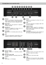
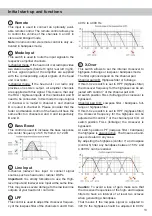
Page 12: ...d D in bandpass mode 2 Mode Input Switch to route input signals to respective amplifier channels 3 Bass Boost Control for adjusting the bass boost on channels C and D from 0 to 12 dB 4 Line Input RCA inputs for connecting lowlevel line sig nals 5 LPF Control for adjusting the lowpass filter of the channels C and D from 40 Hz to 4 000 Hz 6 X Over Switch for activating the filters for each channel p...

Page 13: ...ly forbidden to use the High level Input and lowlevel Line Input at the same time This may cause severe damage to the lowlevel line outputs of your head unit car radio 5 LPF This control is used to adjust the crossover frequen cy of the lowpass filter of the channels C and D from 40 Hz to 4 000 Hz 6 X Over This switch allows to set the internal crossover to highpass fullrange or lowpass bandpass m...

Page 14: ... of the channel pairs A B and C D to the output voltage of the connected signal source This is not a volume control it s only for adjusting the amplifier gain The control range of the RCA Line Input lowlevel is 0 5 6 Volts and 1 14 Volts for the Highlevel Input If the Highlevel Input is used in combination with a standard car radio we recom mend an input sensitivity of roughly 9 Volts For this pur...

Page 15: ... together with the head unit car radio This input needn t to be as signed if the Highlevel Input is used 15 GND The ground cable should be connected to a com mon ground reference point this is located where the negative terminal of the battery is grounded to the metal body of the vehicle or to a prepared metal location on the vehicle chassis i e an area which has been cleaned of all paint residues...

Page 16: ... choose switch position 4CH see page 13 item 2 Mode Input Make sure that the polarity is correct If one or more connections have reversed polarity it may affect the performance of the amplifier If this input is used the remote input REM does not need to be connected as the amplifier will automatically turn on once a loudspeaker signal is applied 3 Adjustment of the input sensitivity Attention It i...

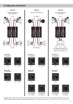
Page 17: ...ly con nected in phase i e plus to plus and minus to minus Exchanging plus and minus causes a total loss of bass reproduction The positive terminal is indicated on most speakers The im pedance of each channel must not be less than 2 Ohms 4 Ohms in bridged mode otherwise the amplifier protection will be activated Exam ples for speaker configurations can be found on page 18 17 Smart highlevel input ...

Page 18: ...cm LS ca 70 Hz for 5 25 13 cm LS ca 100 Hz for 4 10 cm LS 4 channel Component system coaxial system Left Right Left Right Front Rear 3 channel Component system subwoofer Left Right Subwoofer C D bridged Front Channel A B Highpass filter HPF Channel C D Highpass filter 50 100 Hz HPF 50 100 Hz Channel A B Highpass filter HPF Channel C D Bandpass ca 3 500 Hz LPF Lowpass filter ca 3 500 Hz Highpass fi...

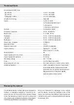
Page 19: ...er technology Class AB Inputs 4 x RCA Cinch 4 x Highlevel speaker input 1 x Remote In 1 x Remote control input Outputs 4 x Speaker output Frequency response 10 Hz 50 000 Hz Bass boost 0 12 dB 45 Hz Highpass 15 Hz 4 000 Hz adjustable Lowpass 40 Hz 4 000 Hz adjustable Bandpass 15 Hz 4 000 Hz adjustable Slope high lowpass 12 dB Oct Distortion THD 0 02 Signal to noise ratio 108 dB A weighted Input sen...

Page 20: ...Audiotec Fischer GmbH Hünegräben 26 57392 Schmallenberg Germany Tel 49 2972 9788 0 Fax 49 2972 9788 88 E mail helix audiotec fischer com Internet www audiotec fischer com ...

Reviews: