


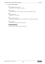

5.5.3
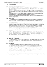
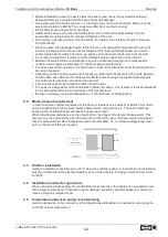
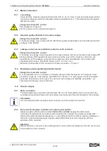
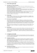
U/f-characteristic curve
Diagram setting signal and U/f curve (quadratic)
F
out
[Hz]
F
max
= 50 Hz
01.02.2013
v_u_f_fcon_basic_setsig.vsd
1
2
3
4
5
6
7
8
9
10
Analog In 1
0
45
50
40
35
30
25
20
15
10
5
2
4
6
8
10
12
14
16
18
20
0...10 V
0...20 mA
10
20
30
40
50
60
70
80
90
100 0...100 % PWM
F
edge
= 48.5 Hz
U
out
100 %
0.5
1
5
U
start
= 0 %
F
off
F
on
Analog In:
Speed setting signal (0 - 10 V, 0...20 mA, 0...100 % PWM)
Fout:
Output frequency
Uout:
Output voltage
Ustart:
Start-up voltage
Foff:
Shutdown Freq.
Fon:
Switch on Freq.
Fedge:
Edgefrequency
Fmax:
Maximum frequency
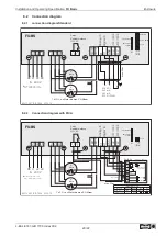
5.6
Motor protection
Motor protection is possible by connecting thermostats
“
TB
”
(thermal contacts) or thermistors
“
TP
”
(PTC).
The jumper
“
J1
”
in the connection space must be plugged according to the used thermal protectors.
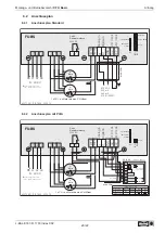
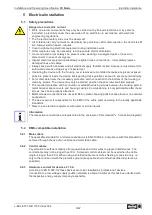
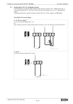
Motor with thermistors
“
TP
”
For motor with thermistors
“
TP
”
the jumper
“
J1
”
must be plugged at the top.
A maximum of six individual thermistors (DIN 44081 or DIN 44082) may be connected in series to
a single device.
J1
TP
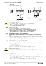
Motor with thermostats
“
TB
”
For motor with thermostats
“
TB
”
jumper plugged at bottom (factory setting).
J1
TB
When a connected thermostat or thermistor responds (interruption between the two terminals
“
TB/TP
”
) the device switches off and does not switch back on.
Relais
“
K1
”
is de-energized, terminals
“
13
”
-
“
14
”
interrupted. The internal signal lamp
fl
ashes in code
|
15
|
(
Diagnostics / faults).
Possibilities for re-starting after the drive has cooled down (terminals
“
TB/TP
”
bridged) by:
•
By switching the mains voltage off and then on again.
•
Via a digital input for remote control (ON/OFF enable).
Danger due to electric current
An outside voltage may never be connected to the terminals
“
TB/TP
”
and/or!
Installation and Operating Speci
fi
cation
FU Basic
Electrical installation
L-BAL-E187-GB 1703 Index 002
Part.-No.
11/22
Summary of Contents for 05459-001
Page 68: ......


