


5.3
Mains connection
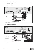
5.3.1
Line voltage
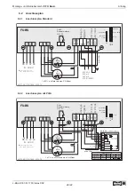
Power from the mains is connected to terminals: PE, L1, L2, L3. Here, it must be strictly observed that
the mains voltage lies within the allowable tolerance speci
fi
cations (
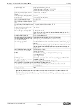
Technical data and nameplate
af
fi
xed to the side).
Danger due to electric current
Not suitable for IT system!
Do not operate on Grounded Delta System!
5.3.2
Required quality attributes for the mains voltage
Danger due to electric current
The mains voltage must comply with the EN 50160 quality characteristics and the de
fi
ned standard
voltages in IEC 60038!
5.3.3
Leakage current, securely attached, protective earth conductor
Danger due to electric current
The maximum leakage current depends on the type of device and the connected mains voltage (
Technical Data). With regard to
fi
xed connection and the type of PE conductor connection, the
speci
fi
cation for the leakage current must be observed under consideration of the locally valid
standards (for Europe
EN 50178 Section 5.2.11 or 5.3.2.1 etc.).
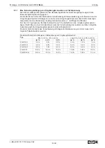
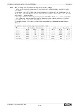
Minimum cross-section for PE conductor for
fi
xed connection = 1.5 mm
2
!
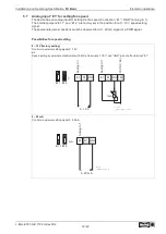
5.4
Residual-current-operated protective device
Danger due to electric current
For an installation of r.c.d. protection, it shall be observed that this must be of
“
universal-current
sensitivity
”
(Type B). In accordance with EN 50 178, Section. 5.2. other types of current-operated
protective devices may not be used. To ensure as high a degree of reliability as possible , we
recommend a tripping current of 300 mA.
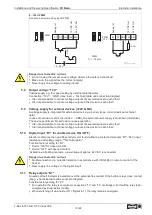
5.5
Inverter output
5.5.1
Motor connection
The motor leads are connected to the terminals: PE, U, V, W. Several fans can be connected to the
controller-the maximum total current of all motors must not exceed the current rating for the controller.
Information
It is recommended that a separate motor protection unit be foreseen for each fan.
5.5.2
Disconnection between controller and motor (repair switch)
Ideally, a repair switch should be installed
before the controller
(supply line disconnect).
In the case of complete disconnection (entire load) after the controller, the enable (controller OFF /
ON) must be disconnected simultaneously. I.e., an additional control contact is needed. Switching on
the motor while simultaneously issuing the enable (ON) achieves secure energizing with low
saturation of the controller.
Attention!
When switching on the motor plus existing release: under certain circumstances, this can occur under
full modulation of the controller.
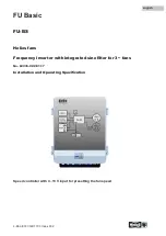
Installation and Operating Speci
fi
cation
FU Basic
Electrical installation
L-BAL-E187-GB 1703 Index 002
Part.-No.
10/22
Summary of Contents for 05459-001
Page 68: ......


