


The ‘grundfos Pressure’ signals can be for two alternate purposes in place of the RPS
sensor (Pressure and T7): measuring an electric circuit with a current transformer
(CT) such as a main supply and electric tank element, or monitoring insolation with
a pyranometer. Two signals can be read simultaneously. The Delta-T Pro electrical
requirements are below. At right is the PCB signal layout.
Power Supply
5VDC
Signal Reading Range
0-5VDC
IMPORTANT: Reversing polarity or going outside of signal ranges will damage circuits.
Contact Heliodyne for connector with 12” wire leads, part number: 21816.
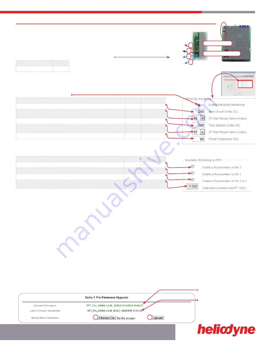
4.1.2.1. Electricity Monitoring Box
FUNCTION DESCRIPTION
DEFAULT
SETTINg LIMIT
Main Circuit Volts AC is the nominal Voltage the CT connected to S1
240VAC
10
≤
V
≤
500VAC
This is the CT’s full scale value (when the controller reads 5VDC, the CT is at full scale)
50A
10, 20, 50, 100,
150, 200A
Tank Circuit Volts AC is the nominal Voltage the CT connected to S2
240VAC
10
≤
V
≤
500VAC
This is the CT’s full scale value (when the controller reads 5VDC, the CT is at full scale)
50A
10, 20, 50, 100,
150, 200A
This is the power frequency (60Hz is standard in USA)
60Hz
40 - 70Hz
Contact Heliodyne for information about compatible CT’s.
4.1.2.2. Insolation Monitoring Box
FUNCTION DESCRIPTION
DEFAULT
SETTINg LIMIT
Select to enable insolation monitoring on Pin 3 (S1)
-
-
Select to enable insolation monitoring on Pin 4 (S1)
-
-
Select to read dual pyranometers, on Pin 3 (S1) AND Pin 4.
-
-
Calibration constant of the installed pyranometer. This is the multiplier the controller will
use to turn the read voltage into insolation.
1.0
1000.0
Contact Heliodyne for information about compatible pyranometers.
4.1.3 SOFtWArE UPDAtE
CaUTIon: sofTWaRe UPDaTes MaY ReseT seTTInGs baCK To DefaUlTs. veRIfY all seTTInGs aRe as ReQUIReD folloWInG an UPDaTe.
4.1.3.0 Software Update through Web Browser - WiFi controllers ONLY
The Pro WiFi and Pro-Lite WiFi controllers can be easily updated through the web browser. To upgrade, download the latest software from
www.heliodyne.com/controls. There are several versions of software on the webpage, for WiFi Pro’s, WiFi Lite’s and Ethernet, so it is crucial
to save the version that goes with your model. The software is typically saved in a compressed folder, with the extension .ZIP. Uncompress
the folder and there will be a .BIN (binary) file and the release notes in a .TXT file inside. READ THE RELEASE NOTES. The .BIN file is the
actual file used by the controller.
Navigate to the SETTINgS page under the SYSTEM box. Click on the link that says ‘Update Software Version.’ A window will pop up and
ask for the user and password, these are the same used to enter into the settings as described in section 3.0. The default user name is
‘Admin’ and the default password is ‘caution’. Once logged in the page below displays.
4.1.3.1 Web Browser Update Process
1.
Select ‘Choose File’ and navigate to the .BIN file on your computer. Once selected the path should display next to ‘Upload’.
2.
Hit ‘Upload’. The controller will download the file you selected into storage. This can take a minute or two for the controller to save the
complete file.
This is the version the controller is
currently operating with.
This is the last version of software that
was loaded into storage (not operating.)
For new controllers this may say ‘No
upgradable firmware has been loaded.’
CHanGInG ConTRolleR sensoRs
15
S O L A R H O T W A T E R
1
2
+5VDC
gND
S1
S2
grundfos Pressure
grundfos Flow
1
4
2
3
FIg. 4.1.2.1
FIg. 4.1.2 B
FIg. 4.1.2.2
FIg. 4.1.3.1A


