6
Do not use any lenses or mirrors to concentrate light (risk of overheating).
Avoid damage to the module from using carbide or diamonds.
Protect solar modules from overvoltage, e.g. voltage peaks from battery-charging devices, alternator generators
etc. (Please ask your specialist retailer in case of any doubt).
If solar modules are connected to energy-storage devices, the safety instructions of the respective manufacturer
must be followed.
Keep children away from solar modules.
In southern regions, a PV module can supply greater power and/or a higher voltage than stated for the standardised
test conditions (standard test conditions). For this reason, in order to define the rated voltage values of components,
rated current values of wires, the size of fuses that are to be connected at the output of PV modules, the Isc and Voc
values listed on the module should be multiplied by 1.25. The highest rated value for overcurrent protection (reverse
current resistance) is 20 A.
5. Module installation
General instructions on module installation
All modules can be fitted both horizontally and vertically independent of the connector sockets.
The modules must not be subject to stress during installation. The modules cannot be used as a rigid linking or fixing
element.
Please be advised that the holes in the frame and in the corners must remain free in order to allow condensed water
to flow out.
Load on the modules
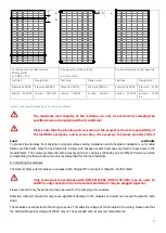
The load capacity of standard solar modules is independent of the installation situation and the system used. Please
observe the installation situations in the following table and the resulting maximum load capacity of the modules.
The values shown (Figure 3) correspond to the design load in accordance with IEC 61215: 2016. The cyclical load test
is carried out according to the standard of a 1.5 times higher test load.
Default situation for continuous mounting rails
Please note that the module can bend under high loads and can strike the mounting rails. Ensure that the mounting rail
displays a sufficient stability and the fixing points are set frequently and correspondingly to prevent the mounting rail
from bending. (Tested with Heckert Solar rails and a support spacing of max. 1m)
Ensure that the maximum mechanical load is not exceeded, in particular while also taking into account the site-
dependent loads, e.g. wind and snow (DIN 1055-4/5).
Do not use any fixing material that might damage the module e.g. due to pointed, sharp or uneven structures. Please
note that the module bends under load and can strike the supporting surface/ mounting rails. Ensure that the connector
sockets and cables, when necessary, are not damaged or exert pressure on the cells.
The total snow load on the ground sk in kN/m results from the respective snow load zone, the building site and the
ground height above sea level. The total wind load for the project site must be determined from the wind zone map,
which takes into account the site situation as well as wind zones. For buildings up to a height of 25 m, the total wind
load may be determined through a simplified procedure. Independent of building heights, the wind load is specified as
velocity pressure q in kN/m
2
.
Summary of Contents for NeMo 3.0
Page 1: ...Installation and operating manual www heckert solar com Status 08 2021...
Page 12: ...12 Excerpt from MC4 crimping instructions Multi contact source...
Page 13: ...13...
Page 14: ...14...
Page 15: ...15...
Page 16: ...16...
Page 17: ...17 Heckert Solar GmbH Carl von Bach Stra e 11 D 09116 Chemnitz...


