HF100
CapecitanceHeightControler
http://www.heavth.com
第
- 13 -
页
共
14
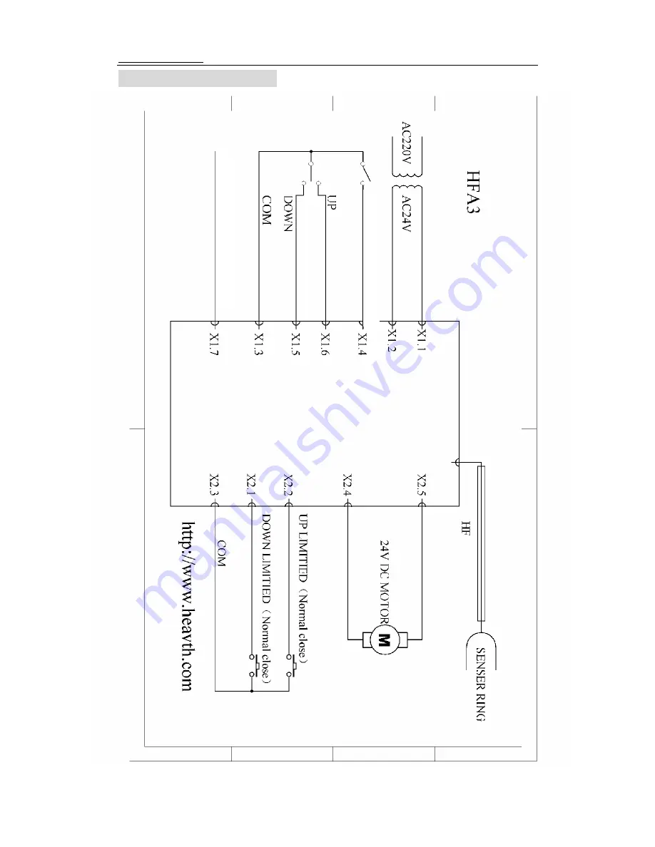
5 DRAWINGS AND DIAGRAMS
C
o
lli
si
on S
ignal
AU
T
O
/M
ANUA
L
(O
P
E
N)
Page 1: ...ance Height Controler TECHNICAL MANUAL VISION 1302 CHANGZHOU HEAVTH SCIENCE TECHNOLOGY CO LTD 136 HUBIN ROAD NIUTANG TOWN CHANGZHOU CITY JIANGSU IN CHINA TEL 86 0519 89182619 FOX 86 0519 89183619 Http www heavth com ...
Page 2: ...2 1 GENERAL DESCRIPTION 7 2 1 1 Front Panel Components 9 2 1 2 Modes 10 2 1 2 1Auto mode 10 2 1 2 2Manual mode 10 Auto and Manual Mode Specifications 10 2 1 3 Limit Switches 10 Limit Switches Specifications 10 3 INSTALLATION 11 3 1 DEFAULT SETTINGS AND DIP SWITCH 12 3 1 1 Position Signal and Remote Operator Control Settings 12 3 1 2 Clock Frequency and Maximum Motor Current 14 4 START UP CHECKS 15...
Page 3: ...state and you must be aware of any additional hazards that can arise 1 4 PRE INSTALLATION CONSIDERATIONS Before installing the HF100 Check to be sure that you have all of the required parts Refer to P6 of this manual Familiarize yourself with the parts of the HF100 by reviewing P4 in this manual Check to be sure that the torch lifter motors you are using with the HF100 are within the acceptable ra...
Page 4: ...anceHeightControler http www heavth com 第 4 页 共 14 页 1 6 PARTS HF100 Part Names HF100 L include connector high frequency cable HF100 L include connector high frequency cable flexible coupling torch clamp ring sensor ...
Page 5: ...ontrolled by a transistorized H bridge Pulse Width Modulated PWM amplifier using armature voltage feedback and adjustable current limitation For automation purposes the integrated control logic offers an In position signal that can also be used to detect cut outs or collision with tip ups Automatic retract of the torch if the high frequency cable is broken or damaged You can override this feature ...
Page 6: ...HF100 CapecitanceHeightControler http www heavth com 第 6 页 共 14 页 2 1 1 FRONT PANEL COMPONENTS Connector X2 TO LIFTER Connector X1 TO CNC HF Connector DISTANCE AUTO TEST SENSITIVITY DOWN UP ...
Page 7: ... lifter when they are triggered The HF100 supports only normally closed limit switches so that malfunctioning limit switches can be recognized by the control Limit Switch Specification Information voltage range 0 TO 5 VDC greater than 4 volts the torch lifter is disabled less than 2 volts the torch lifter is enabled maximum input current 10 mA 3 INSTALLATION The following section provides you with...
Page 8: ...the screws 7 Attach one end of a high frequency cable to the top of the coaxial tube using the Bayonet Neill Concelman BNC connector When determining the length of HF cable to use be sure to choose a length that accommodates for the full lowering of the torch 8 Attach the free end of the HF cable to the control box using the BNC connector 9 Attach the wires from the lifter motor and lifter limit s...
Page 9: ...or ring indicator would turn on and send out collision signal If user changes HF cable or HF cable spec changes indicator might turn on like follow situation HF cable short circuit once it happens indicator turns on torch lift up It could be confirmed by checking the HF cable shield net and Signal connect or not HF cable gets longer it needs to adjust to find the Balance point then THC can work ri...
Page 10: ...ons ensures that the permissible noise field intensity is not exceeded Using a controller clock frequency of 9 kHz meets the 10 kHz interference suppression restrictions however a whistling noise may be heard The position of toggle switches 2 3 and 4 on DIP switch SP2 determine the maximum current for the lifter motor To determine the correct amperage maximum value for the lifter motor refer to th...
Page 11: ...ify that the lifter travel limit switch assignments correspond with torch lifter direction of movement by performing the following checks Move the Up Down switch to the DOWN position and then trigger the corresponding down travel limit switch by hand The lifter should stop when the limit switch is triggered Move the Up Down switch to the UP position and then trigger the corresponding up travel lim...
Page 12: ...n Manual mode lift torch up over 20mm against steel plate 3 Turn the SENSITIVITY and DISTANCE in the middle position 4 Press Auto Test button to turn Auto on if torch lift down means Auto Height is too low then adjust RP4 clockwise to raise the auto height If torch lift up means Auto height is too high turn anti clockwise Please protect the adjust Resistor to avoid damage Do Not exceed 1 4 round o...
Page 13: ...HF100 CapecitanceHeightControler http www heavth com 第 13 页 共 14 页 5 DRAWINGS AND DIAGRAMS Collision Signal AUTO MANUAL OPEN ...
Page 14: ...HF100 CapecitanceHeightControler http www heavth com 第 14 页 共 14 页 Collision Signal ...