


8
Installation Instructions and Owner’s Manual
Unvented Liquid Propane Fired Room Heater
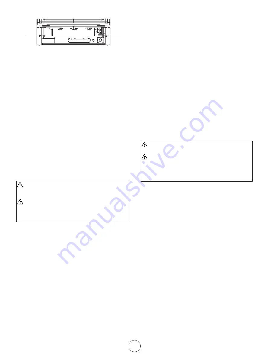
Figure 10
2. Mark screws locations on wall.
3. Remove heater from mounting bracket.
4. If installing bottom mounting screw into hollow
or solid wall, install wall anchors. Follow steps 1
through 4 under Attaching to Wall using Anchor.
If installing bottom mounting screw into wall
stud, drill holes at marked locations using 9/64”
drill bit.
5. Re-place heater onto mounting bracket.
6. Place spacers between bottom mounting holes
and wall anchor or drilled hole.
7. Hold spacer in place with one hand. With the
other hand, insert mounting screw through
bottom mounting hole and spacer. Place tip of
screw in opening of wall anchor or drilled hole.
8. Tighten both screws until heater is fi rmly se-
cured to wall. Do not over tighten.
Note: Do not re-place front panel at this time. Re-
place front panel after making gas connections and
checking for leaks.
CONNECTING TO GAS SUPPLY
WARNING:
A qualifi ed service person must connect
heater to gas supply. Follow all local codes.
WARNING:
This appliance requires a 3/8” NPT
(National Pipe Thread) inlet connection to the
pressure regulator. Use of fl oor mounting feet will
require you to use a 3/8 NPT street elbow to make
gas connection.
CAUTION: Never connect heater directly to the
Propane supply. This heater requires an external
regulator.(which is attached to the supplied hose).
Install the external regulator between the heater and
Propane/LP supply.
The external regulator will reduce the incoming gas
pressure to between 11 and 14 inches of water. If
you do not reduce incoming gas pressure heater
regulator damage could occur. Install external
regulator with the vent pointing down. Pointing the
vent down protects it from freezing rain or sleet.
CAUTION:
Use only new black iron or steel pipe.
Internally-tinned copper tubing may be used in certain
areas. Check your local codes. Use pipe of larger
enough diameter to allow proper gas volume to heater.
If pipe is too small, undue loss of pressure will occur.
Installation must include an equipment shutoff valve,
union and plugged 1/8” NPT tap. Locate NPT tap within
reach of test gauge hookup. NPT tap must be upstream
from heater (see fi gure 11).
*A CSA/AGA certifi ed equipment shutoff valve with
1/8” NPT tap is an acceptable alternative to test gauge
connection. Purchase the CSA/AGA certifi ed equipment
shutoff valve from your dealer.
IMPORTANT:
Install an equipment shutoff valve in an
accessible location. The equipment shutoff valve is for
turning on or shutting off the gas to the appliance.
Apply pipe joint sealant lightly to male threads. This will
prevent excess sealant from going into pipe. Excess
sealant in pipe could result in clogged heater fuel train.
CAUTION:
Use pipe joint sealant that is resistant to
LP-Gas
.
Install sediment trap in supply line as shown in fi gure
11. Locate sediment trap where it is within reach
for cleaning. A sediment trap traps moisture and
contaminants. This keeps them from going into heater.
If sediment trap is not installed or is installed improperly,
heater may not run correctly.
IMPORTANT:
Hold pressure regulator with wrench
when connecting it to gas piping and/or fi ttings.
CHECKING GAS CONNECTIONS
WARNING:
Test all gas piping and connections for
leaks after installing or servicing. Correct all leaks
at once.
WARNING:
Never use an open fl ame to check for
a gas leak. Apply a mixture of liquid soap and water
to all joints. Bubbles forming show a leak. Correct
all leaks at once.
PRESSURE TESTING GAS SUPPLY PIPING
SYSTEM
High Pressure
Test pressure in Excess of ½ psig (3.5kPa)
1. Disconnect appliance with its appliance main
gas valve (control valve) and equipment shutoff
valve from gas supply piping system. Pressures
in excess of ½ psig will damage heater
regulator.
2. Cap off open end of gas pipe where equipment
shutoff valve was connected.
3. Pressurize supply piping system by either using
compressed air or opening main gas valve on
or near gas meter.
4. Check all connections and joints in gas supply
piping system. Apply mixture of liquid soap and
water to gas joints. Bubbles forming show a
leak.
5. Correct all leaks at once.
6. Depressurize and relieve pressure in supply
piping system.
7. Reconnect heater and equipment shutoff valve
to gas supply.
8. Reconnected
fi ttings must be checked for leaks
in next section.
Screw
hole
Screw
hole