HeatSeal 107-ESCK Operating & Service Parts Manual Download Page 18

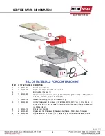
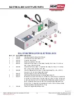
ELECTRICAL BOX & HOT PLATE PARTS 

BILL OF MATERIALS FOR ELECTRICAL BOX 

ITEM   QTY  PART NUMBER  DESCRIPTION 

1818-026 

Circuit Board Assembly, Energy Smart Wrapper 

1818-001 

Cut off Element Circuit Control Board, 120V 

1821-034 

1 Amp Fuse, MDA, Slo-Blo 

1821-037 

25 Amp Fuse, Fast Blow, 125V, ABC 

6340-067 

Fuseholder Kit 1Amp 

Includes: (1) Fuseholder, Panel Mtg, 30A, 1/4 dia x 1-1/4 LG Fuse 

Size, (1) Fuse, 1 Amp, MDA, Slo-Blo 

6340-068 

Fuseholder Kit 25 Amp 

Includes: (1) Fuseholder, Panel Mtg, 30A, 1/4 dia x 1-1/4 LG Fuse 

Size, (1) Fuse, 25 Amp, Fast Blow, 125V, ABC 

6340-069 

Power Cord Replacement Kit 

Includes: (1) Strain Relief, Straight Thru, .425—.475ID, (1) 

Power Cord, 12/3, SJO, 6’LG, W/Nema 5/20P, Strip 8” 


5805-419 

Power Cord Assembly, GFCI, 120V/12GA/20A Plug 

6340-070 

Hot Rod Board Mounting Kit 

Includes: (4) Clip type plastic Stand-Off,  

6340-071 

Electrical Box Component Kit

 Includes: (2) 2 (4 blade term) Terminal Block, (2) Insulated Slip

-on Terminal, 12/10 Wire, Female, (1) Terminal, Ring, Ins, Yellow, 12-10 Wire, 1/4 Stud Size, 
(1) Connector, Wire-Nut, Yel 10-12 (4) Stainlesss Steel Phillips head machine screw #6-32 x 
5/8 LG, (4) Stainless Steel K Type Lock Nut, 6-32, (4) Stainless Steel Philips head screw, 
#10-32 x 3/8” Lg, (1) Ground Nut, (2) Snap Bushing, 11/16 ID x 7/8 OD x 1/8 Max, (8) Stain-
less Steel Hex Washer head Screw #10-32 x 1/2 Lg 

10 

1872-008 

15 Amp-120V Toggle Switch W/Slip On Term 

10 

Revised 201

7


 18 

Summary of Contents for 107-ESCK

Page 1: ...READ ALL INSTRUCTIONS CAREFULLY BEFORE OPERATING EQUIPMENT OPERATING SERVICE PARTS MANUAL 107ES ESCK ENERGY SMART WRAPPER MODEL 107 ES MODEL 107 ESCK Revised 2017...

Page 2: ...ts Electrical Requirements 3 Preliminary Setup 5 Attaching 107ESCK to 107A 5 Recommended Maintenance 8 Troubleshooting Guide 9 Hot Rod Circuit Board Test 10 Replacing Rocker Arm Assembly 12 Service Pa...

Page 3: ...damage the thin heating foil and Non stick cover plate Seal plate damage voids the warranty 1 2 ENERGY SMART TECHNOLOGY The Energy Smart Wrapper is an innovative system that incorporates an Instant On...

Page 4: ...ic film selected for wrapping 3 THERMISTOR TEMPERATURE CONTROL Due to the rapid response of the heating foil and residual heat that can remain from previous cycles a thermistor is incorpo rated as a t...

Page 5: ...the screw holes C and the support bar holes D With the nylock hex nut and washer on the rod insert support rod through the 107 A frame side plate assembly then through the conversion kit and out the o...

Page 6: ...ition the cardboard core of the film roll against the taper of the fixed end cap Make sure the film is threaded from the bottom of the roll and under film roller H see threading diagrams page 6 Replac...

Page 7: ...the wrapper starting with the nearest slot to the hot plate first A Drape unused film in the front of the roller B FILM SELECTION To change film to a different film width Lift up both handles 1 Move e...

Page 8: ...d burn off on the hot plate It s recommended that the Non stick cover be replace every three 3 months or as needed depending on the level of daily wear and tear The Non stick cover should be changed i...

Page 9: ...cuit being utilized is not overloaded with other devices If a surface defect is present discontinue use of product and contact Troy Roberts at 800 342 6329 ext 276 or troberts heatsealco com Seal Plat...

Page 10: ...e Rocker Arm Kit 625ES Part 6340 078 107ES Part 6135 038 Verify the Timer Board is working properly Upon actuation of the Seal Plate the sequence of events should be as follows 1 The Red Indicator Lig...

Page 11: ...KING THE THERMISTOR OF THE HOT ROD With the power turned OFF remove the hot rod black wires from Terminals 5 and 6 Using the meter measure the re sistance of the thermistor by connecting the leads of...

Page 12: ...d the other two to slip on terminals for all marked in picture 3 2 with blue stickers Unscrew the green grounding wire D from the inside the box Separate the two wires being held by the wire nut E 4 L...

Page 13: ...Assemble Rocker Arm and Spring K Position the spring under the red rocker arm between base plate M and attach the shoulder bolts L Tighten the shoulder bolts and the BACK OFF HALF TURN Housing MUST P...

Page 14: ...TIMER BOARD ASSEMBLY Revised 2017 14...

Page 15: ...Block Replacement Kit Includes 1 Upper Left Gray Axle Bearing Block 1 Upper Right Gray Axle Bearing Block 2 Lower Gray Axle Bearing Block 4 Stainless Steel Wing Nut 1 4 20 Solid Body 4 Rubber Luster C...

Page 16: ...Nema 5 20P Strip 8 1 5805 419 Power Cord Assembly GFCI 120V 12GA 20A Plug 5 1 6340 062 Hot Rod Replacement Kit Includes 1 Cutoff Rod TEC100 22 1 2 LG 1 Cutoff Rod Collar 3 4OD 25 64 ID 1 4 THK 8 32 H...

Page 17: ...Rocker Arm Replacement Kit does not include the seal plate 1 Pivot Bracket 1 Red Indicator Light 1 Snap action Switch 2 Shoulder Bolts 1 Compression Spring 2 Stainless Steel Philips Screws 2 K Type Lo...

Page 18: ...des 1 Strain Relief Straight Thru 425 475ID 1 Power Cord 12 3 SJO 6 LG W Nema 5 20P Strip 8 1 5805 419 Power Cord Assembly GFCI 120V 12GA 20A Plug 8 1 6340 070 Hot Rod Board Mounting Kit Includes 4 Cl...

Reviews: