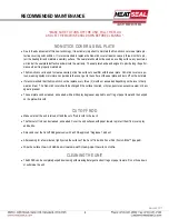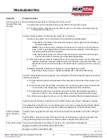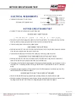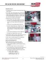
Following Disassembly of the Unit
To Replace the Red Rocker Arm, Switch, Light or Spring:
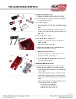
6. Press the plug (G) (Floor model ES) or grommet (H) (625ES) into
hole in the back of red rocker arm.
7. Assemble the Switch (I)
Attach the wires to the OUTSIDE terms and thread lock the wire
screws
Attach the switch assembly to the back of the red rocker arm
with the nuts on the inside and the switch toward bottom of the
rocker arm.
8. Attach the light wires to the light.
9. Mount the Seal Plate to the Rocker Arm
Using the (4) screws and star washers (J), thread lock the
screws to the plate.
DO NOT OVER TIGHTEN SCREWS
10. Route the Seal Plate wires through the grommet (625ES) or
towards the electrical box (floor model ES).
11. Assemble Rocker Arm and Spring (K)
Position the spring under the red rocker arm, between base
plate (M) and attach the shoulder bolts (L).
Tighten the shoulder bolts and the BACK OFF HALF TURN.
Housing MUST PIVOT FREELY.
Rewiring and Reassembling the Unit:
12. Reinstall rocker arm assembly in reverse order as on page 1.
Reconnect the wires (See page 3 for Timer Board close up):
Wire #7 should be matched with wire #7 from fuseholder and
wire nut together.
Wire #190 terminates to the top slot on front terminal board.
The two high luster wires—one goes to the neutral terminal
board in back and the other terminates under the large circuit
board.
Non-terminal wires should be terminated into the green termi-
nal connector block (page 1 A) as follows:
- Thin black wire into “THERM 1 & 2”
- 22 gauge white wires into “PEPI 1 & 2”
- Wires #10 & #15 go into “LIGHT - & +”
G
J
K
L
H
M
I
7
REPLACING ROCKER ARM PARTS
K
L
11
8
10
Revised 201
7
13


