Heatilator ND4842MI Owner'S Manual Download Page 45


Heatilator • Novus Mesh DV • 4031-552 Rev I • 11/07 

45

Figure 12.5  Installing the Hood

Bottom Latch Cover

Firescreen

(Lower Floor Cover-not shown-

shipped underneath)

Firescreen Rod

Hood

Top Latch Cover

Figure 12.3  Clean Face Components/Skin Pack

G. Replace Glass Assembly

•  Set the glass panel on the lower two or four glass assembly 

latches, ensuring the glass panel is centered in the 
opening.

•  Pull out and latch all four or seven glass assembly latches 

into the groove on the glass frame.

Handle glass with care.
•  Inspect the gasket to ensure it is 

undamaged.

•  Inspect the glass for cracks, chips or 

scratches.

•  Do NOT strike, slam or scratch glass.
•  Do NOT operate appliance with glass 

assembly removed, cracked, broken or 
scratched.

•  Replace glass assembly as a complete 

assembly.

WARNING

H. Install Clean Face Components

Carefully remove components from skin pack. See Figure 
12.3 for identi

fi

 cation of components.
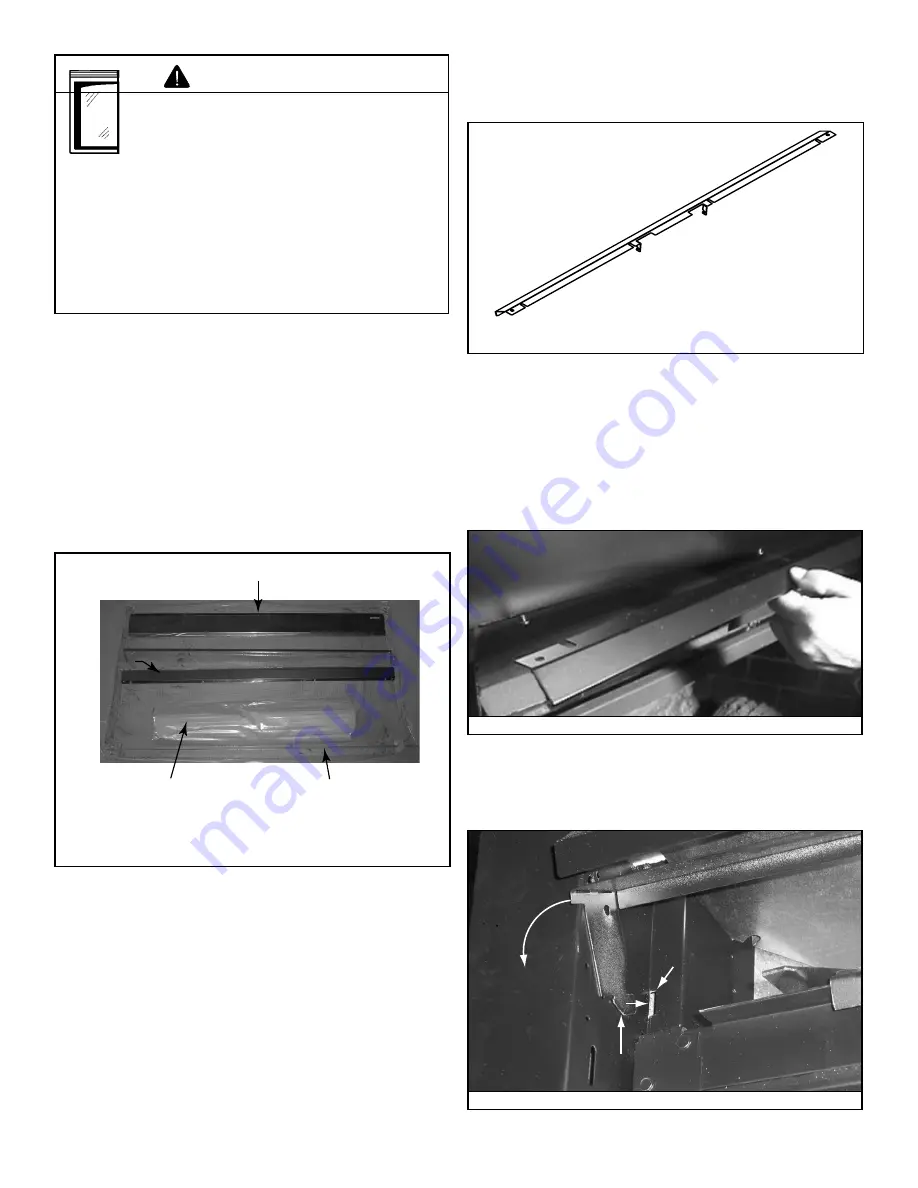
Install Hood

•  Bend screen rod tabs down at a 90-deg. angle. See Figure 

12.4.

Figure 12.4  Screen Rod Tab

•  Install above the glass panel.
•  Hood must be attached or a 

fi

 re hazard may result.

•  Locate the four screws just inside the upper section of the 

appliance.

•  Position hood and slide notches over screw heads.
•  Tighten the four screws.
•  See Figure 12.5.

Install Top Latch Cover

•  Insert top latch cover tabs into slots.  See Figure 12.6.
•  Rotate top latch cover down till the tabs lock in place.

Top Latch

Cover Tab

Slot

Figure 12.6  Installing Top Latch Cover

Summary of Contents for ND4842MI

Page 1: ...ding Immediately call your gas supplier from a neighbor s phone Follow the gas supplier s instructions If you cannot reach your gas supplier call the fire department Installation and service must be p...

Page 2: ...cation on appliance Dealership purchased from Dealer phone Notes We recommend that you record the following pertinent information about your appliance Listing Label Information Location The model info...

Page 3: ...n Cap 32 D Install Roof Flashing and Vertical Termination Cap 33 E Assemble and Install Storm Collar 34 9 Gas Information 35 A Fuel Conversion 35 B Gas Pressure 35 C Gas Connection 35 D High Altitude...

Page 4: ...to any distributor or retailer to whom the product is delivered Some local building codes require the use of tempered glass with permanent marking in such locations Glass meeting this requirement is a...

Page 5: ...eight 8 feet above grade directly in line with the exhaust vent terminal for the horizontally vented gas fueled heating appliance or equipment The sign shall read in print size no less than one half...

Page 6: ...anometer Voltmeter Tape measure Non corrosive leak check solution 1 2 3 4 in length 6 or 8 Self drilling screws One 1 4 in female connection for optional fan Keep appliance dry Mold or rust may cause...

Page 7: ...PURPOSES ONLY Illustrations diagrams are not drawn to scale Actual installation may vary due to individual design preference Fire Risk Provide adequate clearance Around air openings For service acces...

Page 8: ...ng base plate and cantilever floor of the chase should be insulated Vapor and air infiltration barriers should be installed in the chase as per regional codes for the rest of the home Additionally in...

Page 9: ...iance Do NOT install appliance directly on carpeting vinyl tile or any combustible material other than wood WARNING Model A Rough Opening Width B Rough Opening Height C Rough Opening Depth D Rough Ope...

Page 10: ...min from fireplace opening to perpendicular wall B 48 in 1219 mm max Mantel Leg or Perpendicular Wall Top of Appliance Drywall A B Figure 3 4 Clearances to Mantel Legs or Wall Projections Acceptable...

Page 11: ...ulation or other materials away from vent pipe may cause fire Measure horizontal clearances from this surface Measure vertical clearances from this surface Figure 4 1 Clearances from Cap Surfaces see...

Page 12: ...regions Storm Collar Roof Flashing Figure 4 2 Minimum Height from Roof to Lowest Discharge Open ing A Gas Termination Wood or Fuel Oil Termination B 6 in 152 mm min 20 in 508 mm min Direct Vent Gas W...

Page 13: ...pen on a minimum of 2 sides beneath the floor N Vertical clearance between two horizontal termination caps 12 in 30 cm minimum O Horizontal clearance between two horizontal termination caps 12 in 30 c...

Page 14: ...A length of straight pipe is allowed between two 45 elbows see Figure 5 1 ALL vent configuration specifications MUST be followed This product is tested and listed to these specifications Appliance per...

Page 15: ...57 mm from the total H measurement for each 45 elbow installed horizontally A maximum of three 90 elbows or six 45 elbows may be used in any vent configuration Some elbows may be installed horizontall...

Page 16: ...ft max 7 62 m Figure 5 4 Minimum Installation Requirements for Two 45 Elbows Top Vent Horizontal Termination Top Vent Horizontal Termination Three Vertical Elbows See Figure 5 6 for information about...

Page 17: ...5 6 Two or Three Elbows some Horizontal Note Subtract 3 ft 914 mm from the total horizontal measurement for each 90 elbow installed horizontally Subtract 1 1 2 ft 457 mm from the total horizontal meas...

Page 18: ...max Top Vent Vertical Termination No Elbows Top Vent Vertical Termination Two Elbows Figure 5 7 Vertical Termination No Elbows 12 ft 3 66 m min 60 ft 18 29 m max Maximum horizontal run is 100 of vert...

Page 19: ...No Elbows 12 ft 3 66 m min 60 ft 18 29 m max Maximum horizontal run is 100 of vertical but cannot exceed 26 ft 7 92 m Figure 5 9 Vertical Termination Three Elbows some horizontal Note Subtract 3 ft 91...

Page 20: ...rmination One 45 Elbow Rear Vent Horizontal Termination Two Elbows H2 V1 H1 Figure 5 12 Horizontal Termination Two Elbows Model H1 Max Total Vert V Min Total Horiz H1 H2 Novus ft 0 2 1 3 m 0 61 0 31 0...

Page 21: ...from the total horizontal measurement for each 90 elbow installed horizontally Subtract 1 1 2 ft 457 mm from the total horizontal measurement for each 45 elbow installed horizontally Model H1 Max Tot...

Page 22: ...on Two Elbows Figure 5 15 Vertical Termination Two Elbows Rear Vent Vertical Termination One Elbow 12 ft 3 66 m min 60 ft 18 29 m max 0 min 6 ft 1 83 m max Figure 5 14 Vertical Termination One Elbow N...

Page 23: ...7 23 12 ft 3 66 m min 60 ft 18 29 m max 0 min 6 ft 1 83 m max Maximum horizontal run is 100 of vertical but can not exceed 26 ft 7 92 m Figure 5 16 Vertical Termination Three Vertical Elbows Rear Vent...

Page 24: ...ire Risk Explosion Risk Maintain vent clearance to combustibles as specified Do not pack air space with insulation or other materials Failure to keep insulation or other materials away from vent pipe...

Page 25: ...lling Ceiling Firestop Attic Insulation Shield C Install the Ceiling Firestop Frame an opening 10 in by 10 in whenever the vent system penetrates a ceiling floor see Figure 6 4 Frame the area with the...

Page 26: ...tallation The attic insulation shield has been laser etched with cut lines and ceiling pitches to make field trimming easier Remove one shield from box Note Cut previously installed batt insulation to...

Page 27: ...ing band and fold the sides out Figure 7 5 Insulation Basket Figure 7 3 Retaining Band Fold the center parts of the retaining band up and use to remove the vent cap Figure 7 4 Remove Vent Cap Discard...

Page 28: ...10 Insulation Basket Figure 7 11 First Vent Section Cut the metal retaining band and fold the sides out Fold the center parts of the retaining band out and use to remove the vent cap Discard the vent...

Page 29: ...s and Framing Section 6 for hole location Place the appliance into position Level the appliance from side to side and front to back Shim the appliance as necessary It is acceptable to use wood shims B...

Page 30: ...stories or High rise Applications For installation into a commercial multi family multi level exceeding two stories or high rise application All outer pipe joints must be sealed with high temperature...

Page 31: ...Once both inner and outer flues are started press section A onto section B firmly until all lances have snapped into place Check to make sure they have snapped together see Figure 8 3 and the seams ar...

Page 32: ...nto inner flue the last pipe sec tion see Figure 8 6 Slide together to the desired length making sure that a 1 1 2 in outer flue overlap is maintained between the pipe section and slip section The pip...

Page 33: ...rotate either section see Figure 8 10 so that the seams on both pipe sections are aligned see Figure 8 11 They can then be carefully pulled apart Figure 8 8 Securing Vertical Pipe Sections Figure 8 9...

Page 34: ...the termination cap There are two sections of the standard heat shield One sec tion is factory attached to the wall shield firestop The other section is factory attached to the cap See Figure 3 1 If...

Page 35: ...not be recessed in the wall Siding may be brought to the edge of the cap base Flash and seal as appropriate for siding material at outside edges of cap When installing a horizontal termination cap fo...

Page 36: ...to 12 12 4 0 Over 6 12 to 7 12 1 25 Over 12 12 to 14 12 5 0 Over 7 12 to 8 12 1 5 Over 14 12 to 16 12 6 0 Over 8 12 to 9 12 2 0 Over 16 12 to 18 12 7 0 Over 9 12 to 10 12 2 5 Over 18 12 to 20 12 7 5 O...

Page 37: ...brackets and tighten the nut to complete the storm collar assembly Make sure the collar is tight against the pipe section See Figure 8 17 Slide the assembled storm collar down the pipe section until...

Page 38: ...onnector are connected to the 1 2 in 13 mm control valve inlet If substituting for these components please consult local codes for compliance Pressure requirements for appliance are shown in table be...

Page 39: ...lation is complete all connections must be tightened and checked for leaks with a commercially available non corrosive leak check solution Be sure to rinse off all leak check solution following testin...

Page 40: ...stat see individual thermostat instructions to ensure proper operation of appliance Use low resistance thermostat wire for wiring from ignition system to the wall switch and thermostat Keep wire lengt...

Page 41: ...bly GRN ORG BLK ORG Control Box To Junction Box Battery Pack 3V Adapter BLK BRN RED RED WHT Optional SPST Wall Switch or Optional Remote Valve WHT WHT RED GRN GRN wire only for use with optional wall...

Page 42: ...switch for use with a fan See Figure 10 5 The power supply for the appliance must be brought into a switch box The power can then be supplied from the switch box to the appliance using a minimum of 1...

Page 43: ...in to perpendicular wall A 3 1 2 in 89 mm min from fireplace opening to perpendicular wall B 48 in 1219 mm max Mantel Leg or Perpendicular Wall Top of Appliance Drywall A B Figure 11 2 Mantel Leg or W...

Page 44: ...e surface D Accessories Install approved accessories per instructions included with accessories Refer to Section 16 for available optional ac cessories Explosion Risk Follow rockwool placement instruc...

Page 45: ...or scratch glass Do NOT operate appliance with glass assembly removed cracked broken or scratched Replace glass assembly as a complete assembly WARNING H Install Clean Face Components Carefully remove...

Page 46: ...s of high temperatures To avoid burns or clothing ignition the mesh must remain closed if children will be present during the operation and cool down of the fireplace Mesh supplied from factory clippe...

Page 47: ...1 8 in open for natural gas 3 8 in open for propane 30 in 33 in appliances and full open for 36 in and 42 in propane appliances In the event soot is accumulating in your appliance the air shutter shou...

Page 48: ...ustment Ensure that there are no gas leaks Ensure that the glass is sealed and in the proper position Ensure that the flow of combustion and ventilation air is not obstructed front latch covers and ve...

Page 49: ...e appliance WARNING If you do not follow these instructions exactly a fire or explosion may result causing property damage personal injury or loss of life FOR YOUR SAFETY READ BEFORE LIGHTING 33631D C...

Page 50: ...exactly a fire or explosion may result causing property damage personal injury or loss of life FOR YOUR SAFETY READ BEFORE LIGHTING 29097D This appliance needs fresh air for safe operation and must b...

Page 51: ...e flammable materials in the vicinity of the appliance Do NOT use gasoline lantern fuel kerosene charcoal lighter fluid or similar liquids in this appliance Combustible materials may ignite WARNING Fi...

Page 52: ...uple copper lead Start the pilot and hold the valve knob in If the millivolt reading is less than 15mV replace the thermocouple B Defective valve If the thermocouple is producing more than 15 millivol...

Page 53: ...mbly D Bad thermopile or thermocouple Replace if necessary E Improper vent cap installation Check for proper installation and freedom from debris or blockage 6 Glass soots A Flame impingement Adjust t...

Page 54: ...n ON OFF rocker switch or wall switch to OFF position Remove ignitor wire I from module Place ON OFF rocker switch or wall switch in ON position Hold ground wire about 3 16 in away from I terminal on...

Page 55: ...ball valve is open Verify that inlet pressure reading is within acceptable limits inlet pressure must not exceed 14 in w c B Ignitor gap is too large Verify that spark gap from ignitor to pilot hood...

Page 56: ...covers control compartment Burner burner ports Risk of Fire Delayed ignition or explosion Exposure to combustion fumes Odors WARNING Handle glass assembly with care Note Clean glass after initial 3 4...

Page 57: ...d repaint as necessary 2 Replace appliance if firebox has been perforated Burner ignition and operation 1 Verify burner is properly secured and aligned with pilot or ignitor 2 Clean off burner top ins...

Page 58: ...rence Materials A B 1 1 2 in 38 mm 23 1 2 in 597 mm 6 1 2 in 165 mm 3 in 76 mm 2 3 8 in 60 mm 15 3 4 in 400 mm 8 in 203 mm 1 3 4 in 44 mm 34 1 2 in 876 mm C 19 1 8 in 486 mm 11 5 8in 295 mm Electrical...

Page 59: ...ermination Cap High Wind Includes storm collar and fastener pack PVK 80 Power Vent Kit DVP TV Vertical Termination Cap Includes storm collar fastener pack DVP TB1 Basement window well termination cap...

Page 60: ...I 3 to 12 in 76 to 305 mm DVP24MI 3 to 24 in 76 to 610 mm 10 1 2 in 267 mm 10 7 8 in 276 mm DVP45 45 Elbow 45 4 7 8 in 124 mm 10 in 254 mm 1 in 25 mm DVP FS Ceiling Firestop 7 3 8 in 187 mm 11 3 8 in...

Page 61: ...25 mm 13 1 4 in 367 mm RF12M Roof Flashing Multi pak BEK Trap Cap Brick Extension 13 3 4 in 349 mm 5 in 127 mm 13 3 4 in 349 mm DVP BEK2 DVP HPC Cap Brick Extension 13 7 8 in 352 mm 5 in 127 mm 11 7 8...

Page 62: ...Termination Cap PVK 80 For use with IPI and DSI appliances only 1 in 25 mm 14 in 356 mm 3 8 in 10 mm 1 in 25 mm 7 1 4 in 184 mm 7 3 4 to 10 3 8 in 197 to 264 mm DVP FBHT Fire Brick Termination Cap 7...

Page 63: ...Term Cap Effective Length Effective Length TRAP1 4 1 8 in 5 5 8 in 105 mm 143 mm TRAP2 6 3 4 in 10 5 8 in 171 mm 270 mm Note Heat shields MUST overlap by a minimum of 1 1 2 in 38 mm The heat shield i...

Page 64: ...P HRC SS 10 7 8 in 276 mm 10 1 2 in 267 mm 3 87 Effective Length 5 3 4 to 8 3 8 in 146 to 213 mm 5 1 2 in 140 mm 8 3 8 in 213 mm DVP HRC ZC SS Vent Components Diagrams con t Fillers DVP TRAP to DVP HP...

Page 65: ...Heatilator Novus Mesh DV 4031 552 Rev I 11 07 65 This page intentionally left blank...

Page 66: ...ervice Parts List Service Parts Diagram 30 in Novus Circulating Gas Appliance DV Service Parts ND3630M SERIES Beginning Manufacturing Date July 2006 Ending Manufacturing Date Active 24 23 22 25 1 2 3...

Page 67: ...y 4031 061 4031 061 1 12 Hearth Pan 4031 198 4031 198 1 13 Valve Assembly Pre GA1587915 4031 027 4031 512 1 Post GA1587914 4031 510 1 14 Glass Frame Assembly 4031 539 4031 539 1 15 Screen Assembly 403...

Page 68: ...iagram 30 in Novus Circulating Gas Appliance DV Service Parts ND3630M SERIES Beginning Manufacturing Date July 2006 Ending Manufacturing Date Active 13 SP VALVE ASSEMBLY 1 2 3 4 5 6 7 8 9 10 11 12 13...

Page 69: ...4031 547 1 5 Bulkhead Gasket 4021 043 4021 043 1 6 Valve Plate 4031 146 4031 146 1 7 Valve Bracket Pre GA1587915 4031 506 4031 506 1 Post GA1587914 4031 507 4031 507 1 8 ON OFF Valve 15697 15697 1 9 1...

Page 70: ...I 11 07 Service Parts Diagram 33 in Novus Circulating Gas Appliance DV Service Parts ND3933M SERIES Beginning Manufacturing Date July 2006 Ending Manufacturing Date Active 24 23 22 25 1 2 3 4 5 6 7 8...

Page 71: ...ly 4031 061 4031 061 1 12 Hearth Pan 4031 199 4031 199 1 13 Valve Assembly Pre GA1587915 4031 027 4031 512 1 Post GA1587914 4031 510 1 14 Glass Frame Assembly 4031 540 4031 540 1 15 Screen Assembly 40...

Page 72: ...iagram 33 in Novus Circulating Gas Appliance DV Service Parts ND3933M SERIES Beginning Manufacturing Date July 2006 Ending Manufacturing Date Active 13 SP VALVE ASSEMBLY 1 2 3 4 5 6 7 8 9 10 11 12 13...

Page 73: ...14 4031 547 4031 547 1 5 Bulkhead Gasket 4021 043 4021 043 1 6 Valve Plate 4031 146 4031 146 1 7 Valve Bracket Pre GA1587915 4031 506 4031 506 1 Post GA1587914 4031 507 4031 507 1 8 ON OFF Valve 15697...

Page 74: ...1 07 Service Parts Diagram 36 in Novus Circulating Gas Appliance DV Service Parts ND4236M SERIES Beginning Manufacturing Date July 2006 Ending Manufacturing Date Active 22 26 27 23 25 24 1 2 3 4 5 6 7...

Page 75: ...1 062 1 12 Hearth Pan 4031 497 4031 497 1 13 Valve Assembly Pre GA1587915 4031 027 4031 512 1 Post Ga1587914 4031 510 1 14 Glass Frame Assembly 4000 052 4000 052 1 15 Screen Assembly 4031 830 4031 830...

Page 76: ...iagram 36 in Novus Circulating Gas Appliance DV Service Parts ND4236M SERIES Beginning Manufacturing Date July 2006 Ending Manufacturing Date Active 13 SP VALVE ASSEMBLY 1 2 3 4 5 6 7 8 9 10 11 12 13...

Page 77: ...031 547 1 5 Bulkhead Gasket 4021 043 4021 043 1 6 Valve Plate 4031 146 4031 146 1 7 Valve Bracket Pre GA1587915 4031 506 4031 506 1 Post Ga1587914 4031 507 4031 507 1 8 ON OFF Valve 15697 15697 1 9 16...

Page 78: ...1 07 Service Parts Diagram 42 in Novus Circulating Gas Appliance DV Service Parts ND4842M SERIES Beginning Manufacturing Date July 2006 Ending Manufacturing Date Active 22 26 27 23 25 24 1 2 3 4 5 6 7...

Page 79: ...62 1 12 Hearth Pan 4031 498 4031 498 1 13 Valve Assembly Pre GA1587915 4031 027 4031 512 1 Post GA1587914 4031 510 1 14 Glass Frame Assembly 4000 053 4000 053 1 15 Screen Assembly 4031 831 4031 831 1...

Page 80: ...iagram 42 in Novus Circulating Gas Appliance DV Service Parts ND4842M SERIES Beginning Manufacturing Date July 2006 Ending Manufacturing Date Active 13 SP VALVE ASSEMBLY 1 2 3 4 5 6 7 8 9 10 11 12 13...

Page 81: ...2 1 Post GA1587914 4031 547 4031 547 1 5 Bulkhead Gasket 4021 043 4021 043 1 6 Valve Plate 4031 146 4031 146 1 7 Valve Bracket Pre GA1587915 4031 506 4031 506 1 Post GA1587914 4031 507 4031 507 1 8 ON...

Page 82: ...82 Heatilator Novus Mesh DV 4031 552 Rev I 11 07 D Optional Components Arts Crafts Style Faux Front Modernist Style Faux Front...

Page 83: ...h DV 4031 552 Rev I 11 07 83 Center piece is not part of the refractory for the 3630 model TB36 Traditional Brick Refractory Center piece is not part of the refractory for the 3630 model HB36 Herringb...

Page 84: ...84 Heatilator Novus Mesh DV 4031 552 Rev I 11 07 This page intentionally left blank...

Page 85: ...Heatilator Novus Mesh DV 4031 552 Rev I 11 07 85 This page intentionally left blank...

Page 86: ...86 Heatilator Novus Mesh DV 4031 552 Rev I 11 07...

Page 87: ...inadequate ventilation or drafting caused by tight sealing construction of the structure air handling devices such as exhaust fans or forced air furnaces or other causes 5 use of fuels other than tho...

Page 88: ...5000162 5016609 5076254 5113843 5191877 5218953 5263471 5328356 5341794 5347983 5429495 5452708 5542407 5601073 5613487 5647340 5688568 5762062 5775408 5890485 5931661 5941237 5947112 5996575 6006743...

Reviews: