HT# 059296-00A
PLL Installation and Operation Manual
5
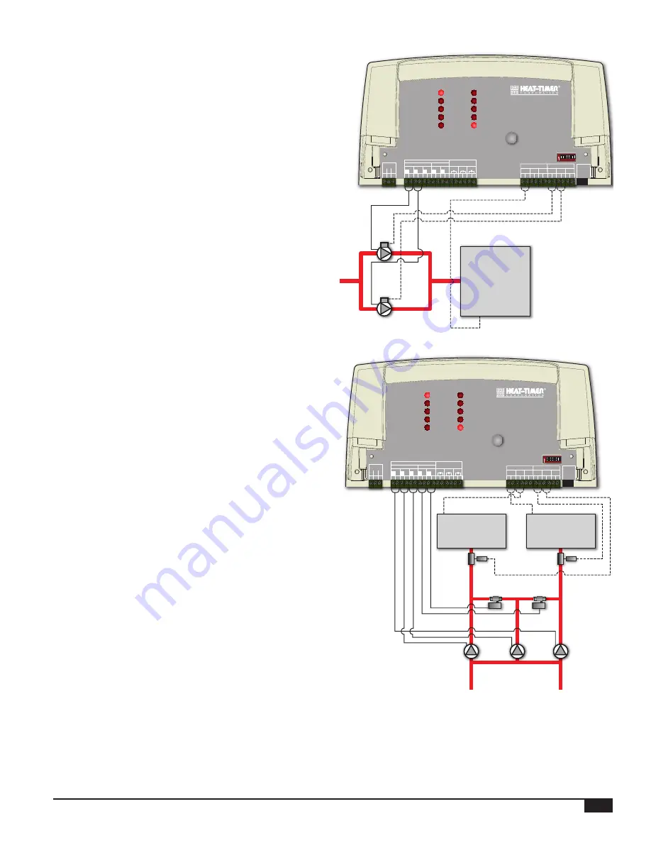
1-Call, 2-Flow (2-Pump)
• This mode is designed to rotate two system pumps in a hydronic
application. It is primarily used with Variable Frequency Drive
(VFD) pumps.
• The operation of this mode is similar to the 1-Call/1-Flow
Mode listed previously. The only exception is that each pump
will have its own flow input. That means that pump call must
be connected to Pump 1 call input terminals (C1) (20 and 21).
Pump 1 flow input must be connected to Flow 1 input terminals
(F1) (26 and 27) and Pump 2 flow input must be connected to
Flow 2 input terminals (F2) (28 and 29).
1 2 3 4 5 6 7 8
On
VFD
Pump2
VFD
Pump1
Boiler or
Heating Source
1 2
DO NOT APPLY ANY VOLTAGE
TO INPUT TERMINALS
10 11 12 13 14 15 16 17 18 19
L N
RS-485
VALVES
A1
A2
A3
PWR
24
20
22
21
23
25
29
27
26
28
30
CAUTION:
Risk of Electric Shock. Use Copper Conductors Only.
Wire all circuits as Class I or Electric Ligh and Power Circuits.
2 RESISTIVE, 120VAC
1/4 HP, 120VAC 60Hz, Pilot Duty 80VA, 120VAC
OUTPUT RATINGS:
ALARM 2
ALARM 3
COM
POWER
ALARM 1
PUMP 2
PUMP 3
VALVE 1
VALVE 2
PUMP 1
ALARM
RESET
PLL
PUMP LEAD-LAG
MAXIMUM 6A TOTAL FOR ALL CIRCUITS
INPUT RATINGS: 120VAC 60Hz, 12VA MAX.
DIP SWITCHES
31
C1
C2
C3
F1
F2
F3
PUMP CALL
FLOW INPUTS
ALARMS
V1
V2
L
N
L
N
6 7 8 9
P2
P3
L
N
4 5
P1
L
N
L
N
PUMPS
OUTPUT (SOURCING)
3
G
auxILIary PuMP
2-Call, 2-Flow (3-Pump)
• This configuration is typically used in a two-Boiler Feed
application. It uses an Auxiliary pump / Pump 3 to replace any
failing boiler feed pump. It does that by turning on a normally
closed solenoid valve to direct the flow from the failing pump to
the auxiliary pump.
• No rotation is available in this mode. The PLL control operates
a single pump per boiler.
• A maximum of two boiler pumps can be connected to a single
PLL.
• If any of the boiler pumps fail to provide proof-of flow in 30
seconds, the PLL will switch its operation to the Auxiliary pump
/ Pump 3 (P3).
• The valve outputs are used to operate solenoid valves to switch
the system flow from the failed pump to the Auxiliary pump /
Pump 3 (P3). Valve 1 output (V1) is turned on when Pump 1
fails and goes into alarm. Valve 2 output (V2) is turned on when
Pump 2 fails and goes into alarm. See "Valve Output Wiring" on
• If a pump fails, the PLL will turn it off and will turn on its Alarm
output, its Valve output, and the Auxiliary pump / Pump 3 (P3)
output. In addition, it will blink its Alarm LED.
• If the second pump fails for over 30 seconds while the first
pump is in alarm, the PLL will turn off the 2nd pump and turn
on its relevant solenoid valve and Alarm LED. In this case, the
Auxiliary pump / Pump 3 (P3) replaces both primary pumps
until the situation is rectified and the Manual Reset button is
pressed.
Boiler 2
Flow
Switch 2
Pump 2
Boiler 1
Flow
Switch 1
Pump 1
Aux Pump 3
Solenoid 1
Solenoid 2
1 2 3 4 5 6 7 8
On
1 2
DO NOT APPLY ANY VOLTAGE
TO INPUT TERMINALS
10 11 12 13 14 15 16 17 18 19
L N
RS-485
VALVES
A1
A2
A3
PWR
24
20
22
21
23
25
29
27
26
28
30
CAUTION:
Risk of Electric Shock. Use Copper Conductors Only.
Wire all circuits as Class I or Electric Ligh and Power Circuits.
2 RESISTIVE, 120VAC
1/4 HP, 120VAC 60Hz, Pilot Duty 80VA, 120VAC
OUTPUT RATINGS:
ALARM 2
ALARM 3
COM
POWER
ALARM 1
PUMP 2
PUMP 3
VALVE 1
VALVE 2
PUMP 1
ALARM
RESET
PLL
PUMP LEAD-LAG
MAXIMUM 6A TOTAL FOR ALL CIRCUITS
INPUT RATINGS: 120VAC 60Hz, 12VA MAX.
DIP SWITCHES
31
C1
C2
C3
F1
F2
F3
PUMP CALL
FLOW INPUTS
ALARMS
V1
V2
L
N
L
N
6 7 8 9
P2
P3
L
N
4 5
P1
L
N
L
N
PUMPS
OUTPUT (SOURCING)
3
G


