HT# 059296-00A
4
PLL Installation and Operation Manual
OvervIeW
The PLL is a Lead-Lag Pump control. It is designed to operate in different modes to satisfy multiple pumping applications. To
three pump systems. With its built-in alarm outputs, the PLL can trigger an alarm whenever a pump fails to provide proof-of-flow
within 30 seconds. It can also be used to provide pump flow check and run-on delay.
The PLL can operate up to 3 pumps. It outputs source 120 VAC power to its pump and solenoid valve outputs. However, alarm
outputs require an external power source.
aLarMIng
• The PLL is equipped with an alarm output for each of the three available pump outputs.
• For local indication, it also has an LED for each of the alarm outputs.
alarming on no-Flow
• If a pump fails to provide proof-of-flow for 30 seconds, by shorting the Flow input terminals, the PLL will turn that pump’s alarm
output on and blink its alarm LED.
• If the mode selected offers a rotation option, then the PLL shall turn on the next pump output and its LED.
ending the alarm
• If any of the pumps is in alarm, its alarm output will remain on until the Alarm Reset button is pressed. This will cause the Alarm
output to turn off.
rOTaTIOn OPTIOns
• The PLL offers lead-lag pump rotation in many of its modes.
• When an operating mode has rotation options, it will have
multiple time-rotation options and an alternating rotation option.
• You can change the time interval of the time-rotation using
the appropriate dip switches for the mode selected. See "Dip
1-Call / 1-Flow (2-Pump Mode) or (3-Pump
Mode)
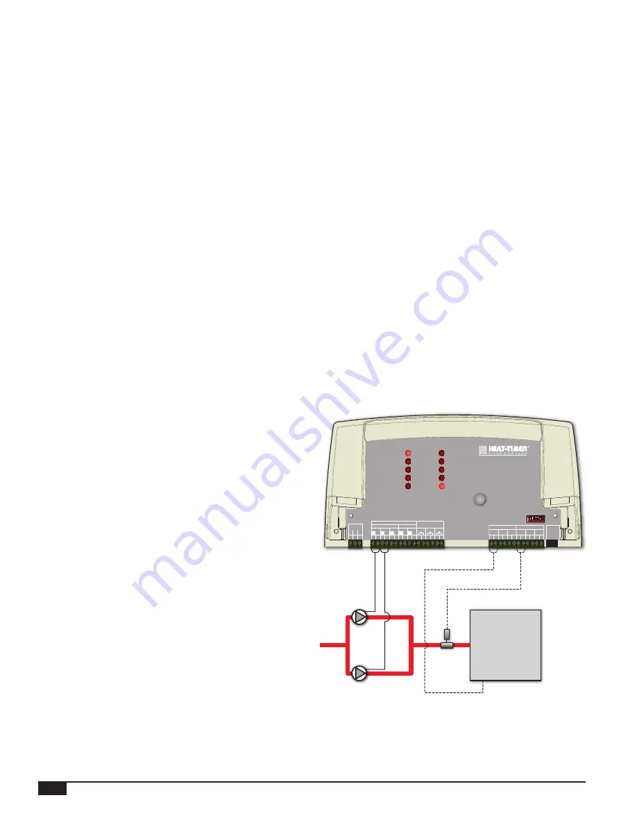
• This mode is designed to rotate two system pumps in a hydronic
application.
• The PLL rotates the pumps based on either timed rotation or
alternating demand (per call). The rotation options are selected
via dip switches.
• The pump call must be connected to Pump 1 input terminals
(C1) (20 and 21). In addition, the flow input must be connected
to Flow 1 input terminals (F1) (26 and 27).
• Alternating demand activates a different pump each time a pump
call is initiated.
• Timed rotation has two options, 1 day, and 7 days rotation.
• When rotation of the lead pump is to take place during a timed
rotation, the operation of both pumps, old lead pump and new
lead pump, will overlap for a few seconds to eliminate a no-flow
period prevent boiler short-cycling.
• In these modes, if a pump fails to provide proof-of-flow for a
period of 30 seconds, the PLL will turn it off. Also, it will turn
on its alarm and turn on the next lead pump.
Flow
Switch
Pump2
Pump1
Boiler or
Heating Source
1 2 3 4 5 6 7 8
On
1 2
DO NOT APPLY ANY VOLTAGE
TO INPUT TERMINALS
10 11 12 13 14 15 16 17 18 19
L N
RS-485
VALVES
A1
A2
A3
PWR
24
20
22
21
23
25
29
27
26
28
30
CAUTION:
Risk of Electric Shock. Use Copper Conductors Only.
Wire all circuits as Class I or Electric Ligh and Power Circuits.
2 RESISTIVE, 120VAC
1/4 HP, 120VAC 60Hz, Pilot Duty 80VA, 120VAC
OUTPUT RATINGS:
ALARM 2
ALARM 3
COM
POWER
ALARM 1
PUMP 2
PUMP 3
VALVE 1
VALVE 2
PUMP 1
ALARM
RESET
PLL
PUMP LEAD-LAG
MAXIMUM 6A TOTAL FOR ALL CIRCUITS
INPUT RATINGS: 120VAC 60Hz, 12VA MAX.
DIP SWITCHES
31
C1
C2
C3
F1
F2
F3
PUMP CALL
FLOW INPUTS
ALARMS
V1
V2
L
N
L
N
6 7 8 9
P2
P3
L
N
4 5
P1
L
N
L
N
PUMPS
OUTPUT (SOURCING)
3
G


