Heat & Glo RED60 Installation Manual Download Page 86

Heat & Glo  •  RED60 Installation Manual  •  2159-980 Rev. D •  11/13

86

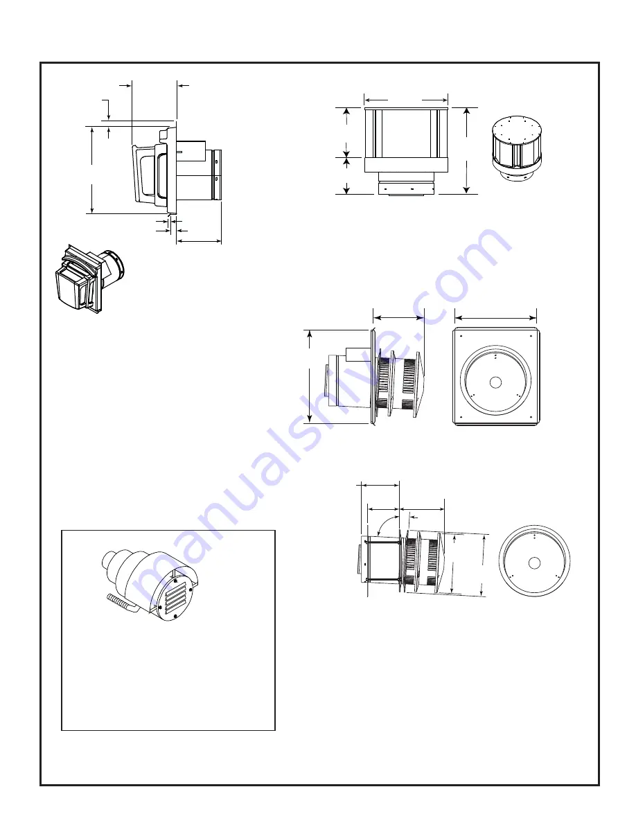
A.  Vent Components Diagrams (

continued

)

Figure 12.4 DVP vent components

7-1/4 in.

12 in.

305 mm

(184 mm)

5-1/4 in.

(133 mm)

12-1/2 in.

(318 mm)

DVP-TVHW

VerticalTermination Cap (Highwind)

PVK-80

(For use with IPI and DSI appliances only.)

1 in.

(25 mm)

14 in.

(356 mm)

3/8 in. (10 mm)

1 in. (25 mm)

7-1/4 in.

(184 mm)

7-3/4 to 10-3/8 in.

(197 to 264 mm)

DVP-FBHT

FireBrickTermination Cap

13 in.

(330 mm)

15 in.

(381 mm)

8-1/8 in.

(206 mm)

 DVP-HRC-SS NOT APPROVED FOR ALL UNITS.

NOT FOR USE WITH LP FUEL

10-7/8 in.

276 mm

10-1/2 in.

267 mm

87°

Effective Length

5-3/4 to 8-3/8 in.

146 to 213 mm

5-1/2 in.
140 mm

8-3/8 in.
213 mm

 DVP-HRC-ZC-SS NOT APPROVED FOR ALL UNITS.

NOT FOR USE WITH LP FUEL

NOTE:  PVK-80 has specific wiring 
and venting requirements for use on 
the RED60 model.  Refer to Section 7 
for installation instructions.

Summary of Contents for RED60

Page 1: ...eration OWNER Retain this manual for future reference RED60 NOTICE DO NOT discard this manual In the Commonwealth of Massachusetts installation must be performed by a licensed plumber or gas fitter SeeTable of Contents for location of additional Commonwealth of Massachusetts requirements WARNING HOT GLASS WILL CAUSE BURNS DO NOT TOUCH GLASS UNTIL COOLED NEVER ALLOW CHILDREN TO TOUCH GLASS A barrie...

Page 2: ...Vent Information 13 G Installation Instructions and Venting Information PVI DVP 14 H Vent Diagrams 21 I Installation Instructions and Venting Information PVK 80 for RED60 Model 29 5 Vent Clearances and Framing A Pipe Clearances to Combustibles 39 B Wall Penetration Framing 39 C Ceiling Firestop Floor Penetration Framing 40 D Install Attic Insulation Shield 41 6 Appliance Preparation A Vent Collar ...

Page 3: ...________________ Gas Section 9 Pg 59 61 Proper appliance for fuel type ___________________________ Was a conversion performed ___________________________ Leak check performed and inlet pressure veri ed ___________________________ Veri ed proper air shutter setting for installation type ___________________________ Finishing Section 10 Pg 62 66 Combustible materials not installed in non combustible ...

Page 4: ...h local codes or in the absence of local codes with National Electric Code ANSI NFPA 70 latest edition or the Canadian Electric Code CSA C22 1 A 110 120 VAC circuit for this product must be pro tected with ground fault circuit interrupter protection in compliance with the applicable electrical codes when it is installed in locations such as in bathrooms or near sinks D High Altitude Installations ...

Page 5: ... eled heating appliance or equipment The sign shall read in print size no less than one half 1 2 in in size GAS VENT DIRECTLY BELOW KEEP CLEAR OF ALL OB STRUCTIONS Inspection The state or local gas inspector of the side wall horizon tally vented gas fueled equipment shall not approve the installation unless upon inspection the inspector ob serves carbon monoxide detectors and signage installed in ...

Page 6: ...r factory trained professionals or technicians supervisedby an NFI certified professional www nficertified org A Design and Installation Considerations Heat Glo direct vent gas appliances are designed to operate with all combustion air siphoned from outside of the building and all exhaust gases expelled to the outside No additional outside air source is required Installation MUST comply with local...

Page 7: ...70 1 8 1781 M 35 1 16 891 N 18 5 8 473 O 9 1 2 241 P 3 3 4 95 Q 1 1 2 38 R 8 1 2 216 S 17 1 8 435 T 12 7 8 327 U 2 1 4 57 V 3 5 8 92 Location Inches Millimeters A 71 7 8 1826 B 17 3 16 437 C 10 3 4 273 D 62 3 4 1594 E 68 1 8 1730 F 22 559 G 4 102 H 5 1 4 133 I 18 1 8 460 J 50 3 4 1289 K 7 178 B J A C D E F G H I K L M N O P STANDARD FAN DUCT ACCESS Q R S U TYP T TYP STANDARD ELECTRICAL ACCESS V TY...

Page 8: ...installation may vary due to individual design preference Figure 3 2 Appliance Locations 1 IN 45 1 IN A E A B C TOP VENT ONE 90 ELBOW ALCOVE INSTALLATION B TOP VENT ONE 90 ELBOW F D B A B C D E F Inches 75 15 16 70 3 8 107 3 8 See Section D Figure 5 6 5 7 31 7 8 18 3 4 Millimeters 1929 1788 2727 810 476 It is important to follow the framing and finishing instruc tions step by step to ensure proper...

Page 9: ...caulked with caulk with a minimum of 300ºF continuous exposure rating or stuffed with unfaced insulation If the appliance is being Figure 3 3 Clearances to Combustibles NOTICE Install appliance on hard metal or wood surfaces extending full width and depth DO NOT install directly on carpeting vinyl tile or any combustible material other than wood WARNING Risk of Fire Maintain specified air space cl...

Page 10: ...Heat Glo RED60 Installation Manual 2159 980 Rev D 11 13 10 NAILING TABS BOTH SIDES Figure 3 4 Nailing Tab Locations ...

Page 11: ... H MIN MINIMUM HEIGHT FROM ROOF TO LOWEST DISCHARGE OPENING 4 4 Termination Location and Vent Information Fire Risk Maintain vent clearance to combustibles as specified DO NOT pack air space with insulation or other materials Failure to keep insulation or other materials away from vent pipe may cause overheating and fire WARNING Figure 4 2 Staggered Termination Caps Gas Wood or Fuel Oil Terminatio...

Page 12: ... X V H A V V H Electrical Service V K V K V L C V N 6 inches non vinyl sidewalls 12 inches vinyl sidewalls O 18 inches non vinyl soffit and overhang 42 inches vinyl soffit and overhang P 8 ft QMIN RMAX 1 cap 3 feet 2 x Q ACTUAL 2 caps 6 feet 1 x Q ACTUAL 3 caps 9 feet 2 3 x Q ACTUAL 4 caps 12 feet 1 2 x Q ACTUAL QMIN termination caps x 3 RMAX 2 termination caps x QACTUAL Covered Alcove Application...

Page 13: ...2 in 216 mm horizontal run and 8 1 2 in 216 mm vertical run A length of straight pipe is allowed between two 45º elbows See Figure 4 4 Figure 4 4 Horizontal Vertical 8 1 2 in 8 1 2 in 1 2 i n E Measuring Standards Vertical and horizontal measurements listed in the vent diagrams were made using the following standards Pipe measurements are shown using the effective length of pipe See Section 12 A f...

Page 14: ...K OF FIRE AND BURNS DO NOT in stall PVI with the access panel facing upward Over heating may occur a If the PVI DVP is being installed in a confined space such as a utility closet mechanical room or attic space with a total volume less than 720 cubic ft an 8 inch by 16 inch hole will be required directly in front of the access panel The confined space where PVI is installed and the space to which ...

Page 15: ... Regulations A minimum of one 90 degree elbow and two feet straight vertical or eight feet vertical venting is required between the appliance and the PVI Once this requirement is met the PVI may be placed at any point in the venting configuration A minimum of 18 inches is required between the PVI and the termination cap to allow room for the pipe to go through a wall or roof Framing and Clearances...

Page 16: ...ng to the ac cess panel Consult officials having jurisdiction regarding regional requirements 8 IN 16 IN TOP CENTER AIR OPENING OVER COVER OPTIONAL FINISH MATERIAL AROUND ACCESS PANEL Figure 4 7 Access Panel Framing Dimensions Figures 4 9 4 10 4 11 and 4 12 show possible framing techniques WARNING Risk of fire and burns DO NOT install PVI DVP with the access panel facing upward Overheating may occ...

Page 17: ...ALL COVER Figure 4 12 and Figure 4 13 show the proper installation of the PVI DVP if a louvered register is being used to provide free air Note If the access cover is solid the 1 2 in clearance should change to a minimum of 2 in For additional scenarios to attach the PVI the optional mounting brackets can be used They can be secured to the side brackets on the PVI using wing nuts supplied The brac...

Page 18: ...to the junction box drill a 7 8 inch diameter hole and lead wire cable assembly through a Romex connector c Attach the end of the harness with the loose wires to the PVI DVP Use supplied zip ties to contain all loose wiring See Figure 4 20 and Figure 4 21 d Attach the end of the harness with the connector to the appliance 2 PVI DVP Connections Refer to the PVI DVP wiring diagram Figure 8 6 a Attac...

Page 19: ...Follow safety inspection procedures recommended by national provincial and or local codes 2 Be certain all electrical connections are properly made and secure 3 Visually inspect the vent system and determine that there is no flue gas spillage blockage or restriction leakage corrosion or other unsafe deficiencies 4 Place the fireplace in operation and determine that the burner and power vent are op...

Page 20: ...rforming any maintenance or repair to the power vent assembly make sure electrical power is disconnected to the fireplace 1 Vent System Inspect all components and connections annually Replace seal or tighten pipe connections if necessary 2 Power Vent Cap Inspect at least annually to clear away any debris blocking any part of the cap 3 Motor The blower motor bearings are sealed and no further lubri...

Page 21: ...s as specified Failure to keep insulation or other material away from vent pipe may cause fire WARNING Note Use DVP Series components only V1 Minimum V1 H1 Maximum 2 ft 610 mm 60 ft 18 3 m 3 ft 914 mm 70 ft 21 3 m 4 ft 1 2 m 80 ft 24 4 m V1 H1 80 ft 24 4 m Maximum Note Must have 24 inches minimum vertical vent prior to attaching any elbow to the appliance Note PVI DVP can be located in any positio...

Page 22: ...Series components only V1 Minimum V1 H1 H2 Maximum 2 ft 610 mm 50 ft 15 2 m 3 ft 914 mm 60 ft 18 3 m 4 ft 1 2 m 70 ft 21 3 m V1 H1 H2 70 ft 21 3 m Maximum Note Must have 24 inches minimum vertical vent prior to attaching any elbow to the appliance Note PVI DVP can be located in any position except V1 WARNING Risk of fire and burns DO NOT install PVI DVP with the access panel facing upward Over hea...

Page 23: ... be located in any position except V1 4 Elbows V1 Minimum Total V Total H Maximum 2 ft 610 mm 30 ft 9 1 m 3 ft 914 mm 40 ft 12 2 m 4 ft 1 2 m 60 ft 18 3 m TOTAL V TOTAL H 60 ft 18 3 m Maximum 5 Elbows V1 Minimum Total V Total H Maximum 2 ft 610 mm 30 ft 9 1 m 3 ft 914 mm 40 ft 12 2 m 4 ft 1 2 m 50 ft 15 2 m Total V Total H 50 ft 15 2 m Maximum 6 Elbows V1 Minimum Total V Total H Maximum 2 ft 610 m...

Page 24: ...Heat Glo RED60 Installation Manual 2159 980 Rev D 11 13 24 Figure 4 27 Vertical Vent Maximum V1 V2 V1 8 ft Min 2 4 m Top Vent Vertical Termination No Elbows V2 50 ft Max 15 2 m ...

Page 25: ...V1 V2 H Maximum 2 ft 610 mm 50 ft 15 2 m 3 ft 914 mm 60 ft 18 3 m 4 ft 1219 mm 70 ft 21 3 m V1 V2 H1 70 ft 21 3 m Maximum Note PVI DVP can be located in any position except V1 WARNING Risk of fire and burns DO NOT install PVI DVP with the access panel facing upward Over heating may occur Note Must have 24 inches minimum vertical vent prior to attaching any elbow to the appliance ...

Page 26: ...rtical Termination Venting with more than 3 elbows Note Use DVP Series components only Note PVI DVP can be located in any position except V1 4 Elbows V1 Minimum Total V Total H Maximum 2 ft 610 mm 30 ft 9 1 m 3 ft 914 mm 40 ft 12 2 m 4 ft 1 2 m 60 ft 18 3 m TOTAL V TOTAL H 60 ft 18 3 m Maximum 5 Elbows V1 Minimum Total V Total H Maximum 2 ft 610 mm 30 ft 9 1 m 3 ft 914 mm 40 ft 12 2 m 4 ft 1 2 m 5...

Page 27: ... TOP OF APPLIANCE MAX ELBOWS 45 90 MAX TOTAL VENT RUN Total V Total H FT MAX VERT DROP V2 FT 3 30 ft 7 ft 4 22 ft 7 ft 5 22 ft 7 ft 1 ft vertical drop decreases horizontal length by 2 ft DIRECT VENT WITH 4 FT MINIMUM VERTICAL OFF TOP OF APPLIANCE MAX ELBOWS 45 90 MAX TOTAL VENT RUN Total V Total H FT MAX VERT DROP V2 FT 3 45 ft 7 ft 4 38 ft 7 ft 5 30 ft 7 ft 6 22 ft 7 ft 1 ft vertical drop decreas...

Page 28: ...TOP OF APPLIANCE MAX ELBOWS 45 90 MAX TOTAL VENT RUN Total V Total H FT MAX VERT DROP V2 FT 3 40 ft 7 ft 4 30 ft 7 ft 5 30 ft 7 ft 1 ft vertical drop decreases horizontal length by 2 ft DIRECT VENT WITH 4 FT MINIMUM VERTICAL OFF TOP OF APPLIANCE MAX ELBOWS 45 90 MAX TOTAL VENT RUN Total V Total H FT MAX VERT DROP V2 FT 3 56 ft 7 ft 4 50 ft 7 ft 5 40 ft 7 ft 6 30 ft 7 ft 1 ft vertical drop decrease...

Page 29: ...rer s instructions will result in conditions which may produce bodily injury and or property damage NOTICE The blower motor present in this appliance will generate sound during operation The effects of the increased sound level can be minimized with careful planning during installation of the system INSTALLATION OF PVK 80 POWER VENT 1 Location of venting system terminations must be made in accorda...

Page 30: ...henever a section of vent pipe passes through a combustible wall 5 The minimum distance from the outside wall to the end of the top shield of the PVK 80 horizontal cap is 14 1 2 inches The maximum distance is 21 inches See Figure 4 36 6 Two support braces are provided and MUST be used to mount the PVK 80 horizontal cap to the wall Screw one end of each brace to the bottom of the cap housing using ...

Page 31: ... wires from PVK 80 Power Vent TERMINAL BLOCK WIRES FROM POWER VENT WIRES TO AUX300 Figure 4 38 8 Plug brown and red wire ends of harness routed in Step 3 onto the brown and red wires from the PVK 80 wiring harness 9 Connect ends of harness routed in Step 4 to the terminal block connecting like colors to one another green to green white to white black to black 10 Replace module heat shield cover pl...

Page 32: ...300 MODULE WALL SWITCH JUMPER WIRE IPI WIRE HARNESS MALE FEMALE WIRE ASSEMBLY 8K1 PVI ORANGE GREEN GREEN VALVE JUMPER JUMPER JUMPER HI LIMIT SWITCHES GROUND TO FIREPLACE CHASSIS JUNCTION BOX TO FAN OUTLET ON JUNCTION BOX PVK 80 POWER VENT WIRES MAY NEED TO BE SPLICED TO REACH APPLIANCE BLACK GREEN WHITE WHITE BLACK GREEN RED BROWN WIRE HARNESS SHIPPED IN ACCESSORY BOX RED BROWN WIRE HARNESS SHIPPE...

Page 33: ... Re pair of the Power Vent should only be done by a qualified service person 1 ACCESS TO THE VACUUM SWITCH TEFLON TUB ING AND BLOWER MOTOR A Turn power to off Remove end cap by removing the four 4 sheet metal screws See Figure 4 41 B Unplug the two wires connected to the vacuum switch and the two wires connected to the blower motor C Loosen and remove the nut for the right angle connector and care...

Page 34: ...ly align the screw holes on the 10 1 2 diameter collar and the inner ring NOTE This inner ring must be returned to its correct ori entation with the 10 1 2 collar for proper fan operation E Secure the cap assembly to the last vent pipe section Position the power vent assembly with the exhaust air directed downward to ensure proper operation F Feed the four 4 wires back through the hole on the coll...

Page 35: ...s around venting and firestop systems Install wall shield and ceiling firestops as specified Failure to keep insulation or other material away from vent pipe may cause fire Note Use DVP Series components only V1 Minimum V1 H1 Maximum 2 ft 610 mm 30 ft 9 1 m 3 ft 914 mm 40 ft 12 1 m 4 ft 1 2 m 50 ft 15 2 m V1 H1 50 ft 15 2 m Maximum Note Must have 24 inches minimum vertical vent prior to attaching ...

Page 36: ...h 2 elbows Note Use DVP Series components only V1 Minimum V1 H1 H2 Maximum 2 ft 610 mm 20 ft 6 m 3 ft 914 mm 30 ft 9 1 m 4 ft 1 2 m 40 ft 12 1 m V1 H1 H2 40 ft 12 1 m Maximum Note Must have 24 inches minimum vertical vent prior to attaching any elbow to the appliance H1 INSTALLED HORIZONTALLY H2 V1 Figure 4 49 ...

Page 37: ...inimum Total V Total H Maximum 2 ft 610 mm 20 ft 6 m 3 ft 914 mm 30 ft 9 1 m 4 ft 1 2 m 40 ft 12 1 m Total V Total H 40 ft 12 1 m Maximum Note Must have 24 inches minimum vertical vent prior to attaching any elbow to the appliance Figure 4 50 4 Elbows V1 V2 Minimum Total V Total H Maximum 2 ft 610 mm 20 ft 6 m 3 ft 914 mm 25 ft 7 6 m 4 ft 1 2 m 30 ft 9 1 m Total V Total H 30 ft 9 1 m Maximum ...

Page 38: ...OP FT V2 3 29 ft 7 ft 4 22 ft 7 ft 1 ft vertical drop decreases horizontal length by 2 ft DIRECT VENT WITH 4 FT MINIMUM VERTICAL V1 OFF TOP OF APPLIANCE MAX ELBOWS 45 90 MAX TOTAL VENT RUN FT Total V Total H MAX VERT DROP FT V2 3 34 ft 7 ft 4 26 ft 7 ft 1 ft vertical drop decreases horizontal length by 2 ft Figure 4 51 Note 1 ft of vertical drop decreases horizontal length by 2 ft NOTICE If a a pi...

Page 39: ...ows center of vent framing hole for top venting The center of the hole is one 1 in 25 4 mm above the center of the horizontal vent pipe A B 75 7 8 in 74 7 8 in A 10 in 12 in B DO NOT PACK WITH INSULATION OR OTHER MATERIAL B Wall Penetration Framing Combustible Wall Penetration Whenever a combustible wall is penetrated you must frame a hole for the wall shield firestop s The wall shield firestop ma...

Page 40: ... the ceiling joists when installed with a attic insulation shield It must be under joists between floors that are not insulated Refer to Figure 5 4 Secure with three fasteners on each side WARNING Risk of Fire DO NOT pack insu lation around the vent Insulation must be kept back from the pipe to prevent overheating Figure 5 3 Installing Ceiling Firestop Figure 5 4 Installing the Attic Shield 3 FAST...

Page 41: ... must be used to prevent blown insulation from getting between the shield and vent pipe and to maintain air space clearance Figure 5 5 Attic Insulation Shield Vaulted Ceiling Installation Remove one shield from box NOTICE Cut previously installed batt insulation to make room for the attic insulation shield Cut the attic insulation shield if application is for vaulted ceiling to fit your ceiling pi...

Page 42: ...on on the starting collar WARNING Risk of Fire A MINIMUM of twenty four inch es vertical pipe is required prior to attaching any elbow to the appliance 3 Place fiberglass rope ring over initial twenty four inch vent section and position tightly to top of appliance 4 Remove bottom metal panel by removing six screws Screw locations are shown in Figure 6 1 All screws are located behind the panel four...

Page 43: ...iance to the framing by using nails or screws through the nailing tabs Figure 6 2 shows the fireplace installed on the floor However this fireplace can be elevated off the floor provided that the fireplace is properly supported by framing materials and the ceiling clearances are maintained Figure 6 2 Proper Positioning Leveling And Securing Of An Appliance POSSIBLE LOCATIONS FOR VENT TERMINATION O...

Page 44: ...around the firebox and back into the room A four inch flexible duct kit has been provided with the appliance One end of the flex duct will connect to the fan bracket assembly located in the lower control chamber See Figure 6 5 Detail A The other end will terminate to an interior wall of the house The intake grille panel provided with the appliance must be used See Figure 6 5 and Figure 6 6 Note Th...

Page 45: ...d 45º elbows that are changing the vent direction from horizontal to vertical one screw minimum should be put in the outer flue at the horizontal elbow joint to prevent the elbow from rotating Use screws no longer than 1 2 in 13 mm If predrilling screw holes DO NOT penetrate inner pipe Required Commercial Multi family Multi level exceeding two stories or High Rise Applications All outer pipe joint...

Page 46: ...g sections Only outer pipes are sealed sealing the inner flue is not required All unit collar pipe slip section elbow and cap outer flues shall be sealed Maintain a 1 1 2 in 38 mm overlap between the slip section and the pipe section Secure the pipe and slip section with two screws no longer than 1 2 in 13 mm using the pilot holes in the slip section See Figure 7 6 C Secure The Vent Sections Verti...

Page 47: ...sassemble Vent Sections Rotate either section see Figure 7 9 so the seams on both pipe sections are aligned as shown in Figure 7 10 Pull carefully to separate the pieces of pipe Figure 7 10 Align and Disassemble Vent Sections Figure 7 9 Rotate Seams for Disassembly ...

Page 48: ...Figure 7 11 Minimum Height From Roof To Lowest Discharge Opening Figure 7 13 insert Bolt into Brackets Figure 7 13 insert Bolt into Brackets NOTICE Failure to properly caulk the roof flashing and pipe seams may permit entry of water Caulk the gap between the roof flashing and the outside diameter of the pipe Caulk the perimeter of the flashing where it contacts the roof surface See Figure 7 12 Cau...

Page 49: ...ll thickness is less than 4 in 102 mm the heat shields on the cap and wall shield firestop must be trimmed A minimum 1 1 2 in 38 mm overlap MUST be maintained Use an extended heat shield if the finished wall thickness is greater than 7 1 4 in 184 mm The extended heat shield may need to be cut to length maintaining sufficient length for a 1 1 2 in 38 mm overlap between heat shields Attach the exten...

Page 50: ...appropriate for siding material at outside edges of cap When installing a horizontal termination cap follow the cap location guidelines as prescribed by current ANSI Z223 1 and CAN CGA B149 installation codes and refer to Section 6 of this manual CAUTION Risk of Burns Local codes may require in stallation of a cap shield to prevent anything or anyone from touching the hot cap NOTICE For certain ex...

Page 51: ...10 120 VAC voltage cannot be shared within the same wall box Junction Box Installation WARNING Risk of Shock Label all wires prior to dis connection when servicing controls Wiring errors can cause improper and dangerous operation Verify proper operation after servicing WARNING Risk of Shock Replace damaged wire with type 105 C rated wire Wire must have high temperature insulation 1 Remove the one ...

Page 52: ...an IntelliFire PlusTM control which operates on a low voltage system Plug the 6 volt AC transformer into the appliance junction box to supply power to the appliance FAN INTERMITTENT PILOT IGNITOR ORANGE WHITE SENSOR WIRE IGNITER WIRE 6VDC TRANSFORMER ELECTRICAL ACCESS KNOCKOUT APPLIANCE ON OFF CONTROL HARNESS THERMO SNAP DISC HARNESS JUMPER HARNESS AUX300 MODULE WALL SWITCH JUMPER WIRE IPI WIRE HA...

Page 53: ...CTION BOX VALVE VALVE BRACKET THERMODISCS LED POWER SUPPLY IF EQUIPPED LED POWER SUPPLY IF EQUIPPED THERMODISCS AUX300 AUX300 8K1 PVI 8K1 PVI Figure 8 5 Controls Location Diagram JUNCTION BOX JUNCTION BOX FAN ASSEMBLY FAN ASSEMBLY MODULE MODULE THERMODISC THERMODISC VALVE VALVE Note If the fan is moved from one side to the other the valve all electrical components including the thermodiscs must al...

Page 54: ...Use threaded nut to secure accessory cable to power vent AXIAL FAN QUICK GROUND CONNECT FAN WHITE JUMPER WIRE BROWN HIGH LIMIT SWITCH BLOWER TO RED60 VACUUM SWITCH Figure 8 6 Internal Wiring for PVI DVP Note Use the two supplied zip ties to secure the wires from touching the blower ...

Page 55: ...ROL ORANGE YELLOW GREEN RED BRN NOT USED FOR THIS MODEL RED BRN L E D CONTROL HARNESS 2 1 BLK LED LIGHTBAR ASSEMBLY TO WIRE HARNESS JUNCTION BOX NOTE The chart below show the colors produced when light control is wired and orientated as shown in this wiring diagram SWITCH TRIPPED COLOR PRODUCED YELLOW GREEN ORANGE RED GREEN BLUE YEL ORG GRN WHITE CLEAR YEL ORG YELLOW ORG GRN PURPLE YEL GRN LIGHT B...

Page 56: ...and out of appliance Set aside See Figure 8 9 and Figure 8 10 Figure 8 10 Lifting Base Pan Up and Out 4 Remove screws from each end of burner assembly Pull burner out of appliance Set aside Figure 8 11 Side Burner Screw SIDE BURNER SCREW 5 Remove left or right side glass pane frame depending on placement of blower from bottom of firebox Remove glass pane and gaskets Gaskets may have become fragile...

Page 57: ... 16 Figure 8 14 Component Tray Figure 8 15 Blower Mounting Bracket Figure 8 16 Blower Removal Through Hole in Firebox Figure 8 17 Fan Removal Through Firebox Bottom Figure 8 18 Removal of Mounting Bracket from Blower 8 Remove mounting bracket from blower by removing the four screws that hold the blower to the bracket They are located on one side of the bracket Save the gasket for use with the new ...

Page 58: ...crews in the appropriate locations See Figure 8 21 Figure 8 19 Blower Gasket Mounting Bracket and Hardware 9 Position the fan so that the arrow on the side of the fan points toward the interior of the appliance Arrows are highlighted by white boxes in Figure 8 20 Figure 8 20 Arrow Indicates Direction of Air Flow 11 Connect electrical cord to the junction box ...

Page 59: ...m from the appliance The lower access cover panel is removable if finishing material is not installed See Figure 9 2 If the finishing materials have been installed around the appliance opening proceed as follows Note Have the gas supply line installed in accordance with local codes if any If not follow ANSI 223 1 Installation should be done by a qualified installer approved and or licensed as requ...

Page 60: ...vailable leak check solution DO NOT use open flame Fittings and connections could have loos ened during shipping and handling WARNING Risk of Fire DO NOT change valve settings This valve has been preset at the factory D High Altitude Installations NOTICE If the heating value of the gas has been reduced these rules do not apply Check with your local gas utility or authorities having jurisdiction Wh...

Page 61: ... air shutter for longer vertical runs See Figure 9 5 Loosen the 1 4 in screw Twist shutter to adjust Shutter may be open for longer horizontal vent runs Do not close the air shutter more than 1 16 in for NG or 1 4 in for LP Tighten the screw NOTICE If sooting occurs provide more air by opening the air shutter Air Shutter Settings RED60 NG LP FULL GRANITE KIT 16 in 1 4 in LIGHT MEDIA KIT 06 in 1 4 ...

Page 62: ...r space clearances to combustibles Inadequate air space may cause overheating and fire Ensure that the one inch back clearance and one inch side clearances are maintained WARNING Risk of Fire DO NOT use screws longer than two inches when attaching finishing materials to non combustible material Screws longer than two inches will compromise clearance and may cause overheating and fire CAUTION Risk ...

Page 63: ...t than air drying light weight compound Painting If desired finishing includes a painted wall 100 acrylic latex with compatible primer is recommended around this appliance Oil based or standard acrylic paints may dis color due to heat exposure Facing Material Facing and or finishing materials must not interfere with air flow through louvers operation of louvers or doors or access for service Facin...

Page 64: ...lap Fit Method Figure 10 4 Overlap Fit Method AIR SPACE 7 IN 1 IN 0 1 1 4 IN 0 1 1 4 IN THICK DRYWALL OR EQUIVALENT STANDARD DECORATIVE FRONT SHOWN FACTORY INSTALLED NON COMBUSTIBLE BOARD 13 3 4 IN NON COMBUSTIBLE BOARD The mesh decorative front is approved for inside fit ap plications Non combustible finishing materials up to 4 inches thick can be installed around the Mesh front left right top an...

Page 65: ...Extending Past The Face Of The Fireplace UNLIMITED 6 IN MIN 2 IN MIN FIREPLACE OPENING TOP VIEW 4 IN MAX ACCEPTABLE NON COMBUSTIBLE MANTEL LEG ZONE Combustible Mantels Note For non combustible fireplace finish material marble stone etc specifications refer to Section 10 A Non Combustible Mantels Figure 10 6 Minimum Vertical and Maximum Horizontal Dimensions of Combustibles Figure 10 7 Minimum Vert...

Page 66: ...e this appliance without a decorative front in place A mesh front is included with the RED60 This is the door approved with this appliance model It must be used To attach the mesh front to the appliance use the two mesh brackets These brackets are mounted to the un derside of the top of the appliance viewing area and are fastened to the appliance by two screws on each bracket See Figure 10 10 Ther...

Page 67: ...ke slam or scratch glass DO NOT operate fireplace with glass removed cracked broken or scratched Replace as a complete assembly Removing Fixed Glass Assembly 1 Remove the decorative front 2 Locate the four spring latches that are on the lower left and right of the fireplace 3 Use both index fingers to release spring latches See Figure 11 1 4 Allow glass to tilt forward Grasp glass on the upper ret...

Page 68: ...e WARNING Delayed Ignition Risk Place rock media according to instructions Do NOT place rock media in area in front of pilot or between burner tracks Do NOT place rock media pieces in a position that they may fall into area in front of pilot Do NOT use any media other than the rock media supplied with this fireplace Do NOT exceed one layer of rock media on base pan Fireplace will not function prop...

Page 69: ...ording to instructions Do NOT place rock media in area between glass and firebox Do NOT place rock media pieces in a position that they may fall into area between glass and firebox Do NOT use any media other than the rock media supplied with this fireplace Fireplace will not function properly Gas leak may occur PILOT SHIELD UNDER JIG PILOT SHIELD UNDER JIG ROCK MEDIA ROCK MEDIA PLACEMENT JIG PLACE...

Page 70: ...ee Figure 2 2 Outside corner trim pieces See Figure 3 7 Angle tabs and 7 Sheet metal screws See Figure 4 1 Rear inside base See Figure 5 1 Front Inside base See Figure 6 1 Outside front trim base See Figure 7 4 Inside Base Mesh See Figure 8 Tools Required Cordless Drill 1 4 inch hex head driver tip Flat Blade Screwdriver Figure 4 Angle Tabs with Screws NOTICE The installation of the porcelain kit ...

Page 71: ...lace rear inside porcelain base piece Place into bot tom of fireplace with tabs away from the burner Center from front to back There will be a gap between the front edge of the base piece and the burner area and also a gap between the back of the porcelain piece and the rear porcelain panel These two gaps should be equal See Figure 11 5 Install front inside porcelain base piece Position into botto...

Page 72: ...m base onto shelf Place so the cutouts are in line with the outside edges of the glass frame See Figure 14 Figure 16 Installing Outside Corner Trim Piece onto Clip TRIM BASE Figure 18 Service Parts Diagram Figure 17 Outside Corner Trim Piece Installed Service Parts 1 1 2 6 2 3 4 5 ITEM DESCRIPTION PART NUMBER Refractory Kit POR60 F 1 Front Corner Panel Qty 2 req 2159 229 2 Panel Side Qty 2 req 215...

Page 73: ... Figure 7 4 Slide each inner side porcelain panel in from the front until it touches the back wall Secure with angle tabs and screws in the pilot holes that are located on the top of the firebox See Figure 6 5 Bend the tabs mentioned on step 3 toward the porcelain panel See Figure 8 Figure 6 Installing Angle Tab to Secure Inner Back Panel Installation 1 Verify the correct base pan is in the applia...

Page 74: ...TAB UP TAB BENT TO TAB BENT TO 90º ANGLE 90º ANGLE Figure 10 Installing Outside Corner Trim Piece onto Clip Figure 11 Installing Outside Corner Trim Piece onto Clip CLIP CLIP WARNING Delayed Ignition Risk Place glass rock according to instructions Do NOT place glass rock in area in front of pilot or between burner tracks Do NOT place glass rock in a position that they may fall into area in front o...

Page 75: ...hat do not have media installed Kit Contents 3 Back panel pieces 19 13 16 inches wide x 16 7 8 inches tall See Figure 1 2 Inner side wall pieces 10 inches wide x 16 7 8 inches tall See Figure 2 Note Optional Porcelain or Granite Kits used with lighted and non lighted media models must be placed in appliance before placing glass media in the appliance NOTICE The installation of the granite kit may ...

Page 76: ...base pan as shown in Figure 9 The screws will be located either on top of or underneath the mesh If underneath mesh lift mesh screen up and remove for access to screw heads Discard mesh 2 Remove pilot shield as shown in Figure 10 Discard PILOT SHIELD Figure 10 Removing Pilot Shield 3 Measure granite pieces to ensure you are installing them in the correct orientation Install back panel pieces first...

Page 77: ...e support pieces between burner rail and front of appliance The notched area of the granite support piece will be positioned over the pilot area and will sit securely on the base pan Proper placement of mesh around pilot is critical to safe operation WARNING Delayed Ignition Risk Place mesh piece with notch on area around pilot DO NOT place mesh piece without notch over pilot Interruption of pilot...

Page 78: ...ning tabs at the top by installing the sheet metal screws into the pilot holes located above the granite See Figure 20 Figure 19 Outer Front Trim Base Installed on Shelf Figure 18 Access Panel Installed GLASS ASSEMBLY ACCESS PANEL Figure 22 Service Parts Diagram 4 5 6 6 6 5 4 3 3 3 2 2 2 1 1 Service Parts GLASS FRAME TAB RETAINING TAB CONTACTS GRANITE Figure 21 Placing Outer Corner Granite Trim Pi...

Page 79: ...n by removing back row and sides of quarter inch sheet metal screws from base pan as shown in Figure 5 The screws will be located either on top of or underneath the mesh If underneath mesh lift mesh screen up and remove for access to screw heads After removing screws replace mesh before installing granite 2 Measure granite to ensure you are installing the pieces in the right orientation Back panel...

Page 80: ... holes located above the granite See Figure 9 and Figure 10 WARNING Delayed Ignition Risk Place rock media according to instructions Do NOT place rock media in area in front of pilot or between burner tracks Do NOT place rock media in a position that they may fall into area in front of pilot Do NOT use any media other than what is supplied with this fireplace Do NOT use more than three 10 lb bags ...

Page 81: ...ece Position piece into bottom of fireplace with tabs facing the burner Center piece from front to back There will be a gap between the front edge of the base piece and the burner area and also a gap between the back of the base piece and the rear firebox panel These two gaps should be equal See Figure 4 3 Install glass frame assembly and spring lock into posi tion according to instructions in app...

Page 82: ...igure 9 and Figure 10 Figure 9 Installing Outside Corner Trim Piece onto Clip Figure 10 Outside Corner Trim Piece Installed Figure 11 Service Parts Diagram 1 1 2 3 3 Service Parts ITEM DESCRIPTION COMMENTS PART NUMBER Metal Refractory Kit RED60 SMR 60NL 1 Panel Side No Lights 2159 237 2 Exterior Panel Cover 2159 239 3 Interior No Light Base 2159 238 I Install the Mesh A mesh front is included with...

Page 83: ...54 mm 1 in 25 mm 12 in 305 mm 14 in 356 mm 1 in 25 mm 8 in 203 mm 6 in 152 mm 10 in 254 mm 1 1 2 in 38 mm 5 in 127 mm 12 in 305 mm UP DVP HVS Vent Support DVP WS Wall Shield Firestop DVP FS Ceiling Firestop DVP45 45º Elbow DVP Pipe see chart Effective Height Length 4 7 8 in 124 mm 13 mm Assembled Height 24 in 610 mm Diameter 10 in 254 mm DVP AS2 Pipe Effective Length Inches Millimeters DVP4 4 102 ...

Page 84: ...ermination Cap 15 1 8 in 384 mm 12 in 305 mm 8 in 203 mm Max Effective Length Note Heat shields MUST overlap by a minimum of 1 1 2 in 38 mm The heat shield is designed to be used on a wall 4 in to 7 1 4 in 102 mm to 184 mm thick If wall thickness is less than 4 in 102 mm the existing heat shields must be field trimmed If wall thickness is greater than 7 1 4 in 184 mm a DVP HSM B will be required H...

Page 85: ...shing Multi pak 31 in 787 mm 24 5 8 in 625 mm 13 1 4 in 337 mm RF12M Roof Flashing Multi pak Cap Shield DRC RADIUS 13 7 8 in 352 mm 9 1 2 in 241 mm 14 in 356 mm COOL ADDM Cap Shield 11 5 8 in 295 mm 5 3 4 in 146 mm 7 1 8 in 181 mm 12 1 8 in 308 mm DVP BEK2 DVP HPC Cap Brick Extension 13 7 8 in 352 mm 5 in 127 mm 11 7 8 in 302 mm DVP TRAPFL Flashing 26 in 660 mm DVP HSM B Extended Heat Shield ...

Page 86: ... 1 in 25 mm 7 1 4 in 184 mm 7 3 4 to 10 3 8 in 197 to 264 mm DVP FBHT FireBrickTermination Cap 13 in 330 mm 15 in 381 mm 8 1 8 in 206 mm DVP HRC SS NOT APPROVED FOR ALL UNITS NOT FOR USE WITH LP FUEL 10 7 8 in 276 mm 10 1 2 in 267 mm 3 87 Effective Length 5 3 4 to 8 3 8 in 146 to 213 mm 5 1 2 in 140 mm 8 3 8 in 213 mm DVP HRC ZC SS NOT APPROVED FOR ALL UNITS NOT FOR USE WITH LP FUEL NOTE PVK 80 ha...

Page 87: ...a wall remote control with child protection lockout feature Keep remote controls out of reach of children See your dealer if you have questions Printed in U S A Copyright 2013 Heat Glo a brand of Hearth Home Technologies Inc 7571 215th Street West Lakeville MN 55044 www heatnglo com Please contact your Heat Glo dealer with any questions or concerns For the location of your nearest Heat Glo dealer ...

Reviews: